Special tool rest for machining inner bore

A tool holder and inner hole technology, which is applied in metal processing equipment and other directions, can solve the problems of easy ripples on the inner hole surface, tool pick marks, poor machining accuracy, etc., to facilitate maintenance operations, reduce labor intensity, and avoid tool shank shaking. Effect

Active Publication Date: 2012-05-30
HARBIN JIANCHENG GRP
View PDF5 Cites 1 Cited by
  • Summary
  • Abstract
  • Description
  • Claims
  • Application Information

AI Technical Summary

Problems solved by technology

[0003] The purpose of the present invention is to solve the problem of poor machining accuracy due to the shaking of the tool during the machining of the inner hole of the slender and thin-walled sleeve. Special knife holder for inner hole
[0005] The advantages of the present invention are: 1. The present invention sends the cutter head to the inner hole of the workpiece through the lengthened long cutter rod. Since the fixing seat supports the long cutter rod, the trembling of the cutter rod is avoided, and the inner hole There is no ripple on the surface, which solves the problem that there are tool marks on the inner wall of the workpiece turned around at both ends

Method used


Image

  • Special tool rest for machining inner bore
  • Special tool rest for machining inner bore
  • Special tool rest for machining inner bore

Examples


specific Embodiment approach 1

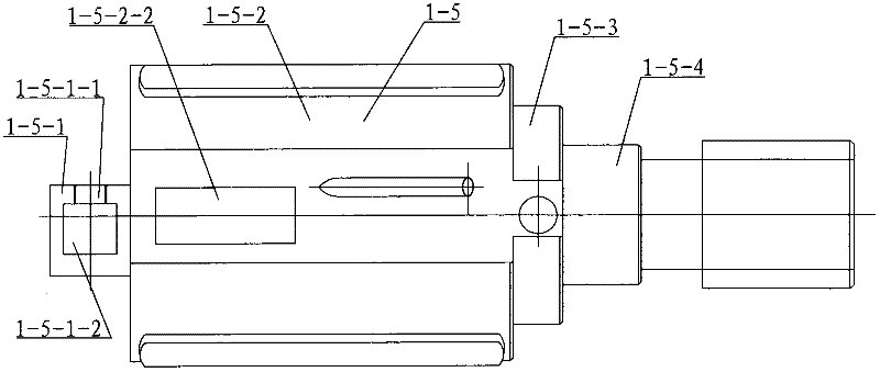
[0007] Specific implementation mode one: combine Figure 1 to Figure 6 Describe this embodiment, this embodiment is made up of arbor assembly 1 and holder assembly 2, and arbor assembly 1 is made up of sleeve 1-2, handle 1-3, knife holder 1-5, long arbor 1-6, joint 1-7. Composed of two support screws 1-1 and four positioning blocks 1-4, the tool holder 1-5 in the axial direction from front to back is the tool loading section 1-5-1 and the positioning section 1-5- 2. The transition section 1-5-3 and the connecting section 1-5-4 of the knife bar, the cross section of the knife loading section 1-5-1 is rectangular, and there are two on the upper plane of the knife loading section 1-5-1 Threaded hole 1-5-1-1, knife loading section 1-5-1 is radially provided with long groove 1-5-1-2 communicating with two threaded holes 1-5-1-1, positioning section 1 The outer surface of -5-2 is evenly provided with four positioning grooves 1-5-2-1, and a positioning block 1-4 is housed in each po...

specific Embodiment approach 2

[0008] Specific implementation mode two: combination image 3 and Figure 4 To illustrate this embodiment, four rectangular grooves 1-5-2-2 are arranged on the outer surface of the positioning section 1-5-2 of this embodiment, and between every two positioning grooves 1-5-2-1 Set up a rectangular slot 1-5-2-2. Rectangular groove 1-5-2-2 is used to install the wiper knife, and trim the inner hole of the processed long thin-walled sleeve with a wiper knife, so that the inner hole of the long thin-walled sleeve meets the accuracy required by the drawing. Other components and connections are the same as those in the first embodiment.

[0009] Working principle of the present invention:

[0010] Before use, first install the cutter head between the two support screws 1-1 and the sleeve 1-2, align the cutter head with the processing part of the workpiece 3, and the tail top 5 withstands the joint 1-7 on the cutter bar assembly 1 , connect the pressure plate 2-5 on the fixed seat...


PUM


Abstract

The invention discloses a special tool rest for machining an inner bore and relates to a tool rest for machining an inner bore, and the special tool rest can be used for solving the problem of poor machining precision because a tool trembles, the inner bore surface easily generates ripples and the inner wall of a U-turn machining workpiece on two ends is provided with a tool connecting mark when the inner bore of a spindly thin-wall sleeve is machined. The special tool rest is composed of a tool bar assembly and a permanent seat assembly, wherein the tool bar assembly is composed of a sleeve,a handle, a tool apron, a long tool bar, a joint, two support bolts and four locating blocks; the tool apron is successively provided with a tool loading section, a locating section, a transition section and a tool bar connection section along the axial direction from front to back; the cross section of the tool loading section is rectangular; each locating slot is provided with the locating block; one end of the long tool bar is connected with the tool bar connection section; the other end of the long tool bar is connected with the joint; the permanent seat is composed of a locating bolt, anupper tilting fillet, a center frame foundation, a bearing bush and a platen; the distance between the upper end surface of the platen and the lower end surface of the center frame foundation is 15mm; and the long tool bar passes through the bearing bush and moves forward and backward in the bearing bush. The special tool rest for machining the inner bore is used for machining a spindly thin-walldeep bore.

Description

technical field [0001] The invention relates to a tool holder for machining inner holes. Background technique [0002] There is no special tool holder when machining the inner hole of the long thin-walled sleeve. Due to the trembling of the tool during processing, ripples are easily generated on the surface of the inner hole. Less than process requirements. Contents of the invention [0003] The purpose of the present invention is to solve the problem of poor machining accuracy due to the trembling of the tool during the machining of the inner hole of the slender and thin-walled sleeve, the surface of the inner hole is prone to ripples, and the inner wall of the workpiece turned around at both ends has traces of the knife, resulting in poor machining accuracy. Special knife holder for inner hole. [0004] The present invention is composed of a knife bar assembly and a fixed seat assembly. The knife bar assembly is composed of a sleeve, a handle, a knife seat, a long knif...

Claims


Application Information

Patent Timeline
Patent Type & Authority Applications(China)
IPC IPC(8): B23B21/00
Inventor 齐晓燕范永滨段波李峰
Owner HARBIN JIANCHENG GRP
Why Eureka
Try Eureka