Endoscope body and digestive endoscope robot
A technology of mirror body and shell, applied in endoscopy, medical science, surgery, etc., can solve the problems of easy fatigue of doctors, affecting the quality of inspection or treatment, and achieve the effect of avoiding hand tremor, simplifying structure and stable structure.
- Summary
- Abstract
- Description
- Claims
- Application Information
AI Technical Summary
Problems solved by technology
Method used
Image
Examples
specific Embodiment approach 1
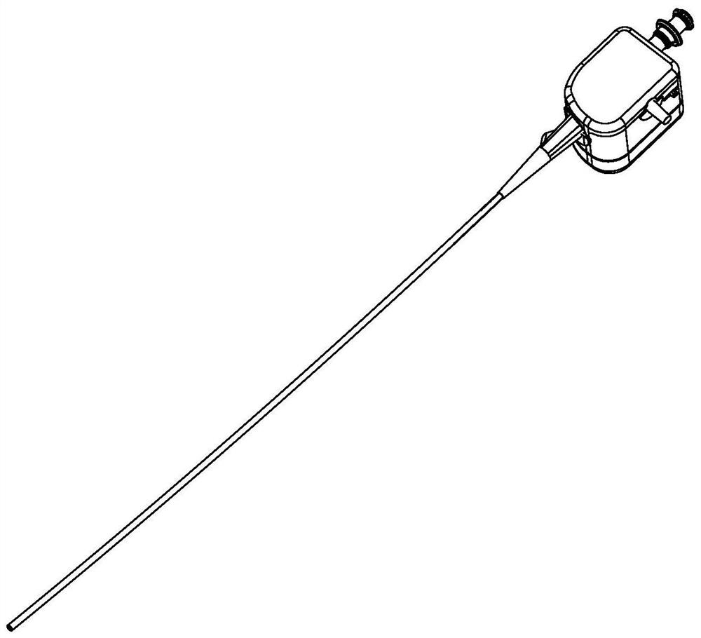
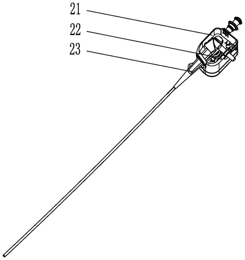
[0014] Specific implementation mode one: combine Figure 1 to Figure 6 Describe this embodiment, this embodiment comprises a driving mechanism housing 21, a driving mechanism 22 and an endoscope handle 23, the endoscope handle 23 is installed in the driving mechanism housing 21, and the driving mechanism 22 is installed in the driving mechanism housing 21 and is located At the lower end of the endoscope handle 23, the drive mechanism 22 controls the bending angle of the end of the endoscope handle 23 by driving the rotation of the steel wire in the endoscope handle 23.
[0015] Before this embodiment is used, the preoperative preparation of the present invention is convenient, and the places in contact with the endoscope body are all disposable parts, which are convenient for disinfection and high in safety. The main body of the robot endoscope is disinfected as a whole. After disinfection, the whole body is connected to the mechanical arm system 6 and connected to the externa...
specific Embodiment approach 2
[0018] Specific implementation mode two: combination image 3 Describe this embodiment, the driving mechanism casing 21 of this embodiment includes an upper surrounding casing 2101, a lower surrounding casing 2102, a ferrule 2103, a bevel gear shaft 2104, a large bevel gear 2105 and a shaft end nut 2106, and the upper surrounding casing 2101 is installed on the lower surrounding shell 2102, ferrule 2103 is mounted on one end face of the upper surrounding shell 2101 in the width direction and one end face in the longitudinal direction, and the bevel gear shaft 2104 is installed on the other end face of the upper surrounding shell 2101 in the width direction. On one end face, the large bevel gear 2105 is installed and sleeved on the bevel gear shaft 2104 , and the shaft end nut 2106 is installed on the end of the bevel gear shaft 2104 . In this way, the small bevel gear 2006 of the rotating device 2 meshes with the large bevel gear 2105 of the driving mechanism housing 21 , whic...
specific Embodiment approach 3
[0019] Specific implementation mode three: combination Figure 4 Describe this embodiment. The driving mechanism 22 of this embodiment includes a first driving unit and a second driving unit. The first driving unit and the second driving unit respectively drive a steel wire in the endoscope handle 23 and drive the corresponding steel wire to zoom. With such arrangement, the driving precision is ensured by driving the two steel wires respectively. Other compositions and connections are the same as those in Embodiment 1 or 2.
[0020] In the prior art with the notification number CN103767659A, the angle control of the endoscope is realized by driving the rotation of the steel wire through the dial of the driving handle. However, the driving mechanism of this embodiment can directly drive the steel wire to move, omitting the dial wheel in the prior art, and then drives the front end of the mirror body to bend in various directions, so it is flexible to use. Moreover, this embod...
PUM
 Abstract
Description
Claims
Application Information
 - R&D
- Intellectual Property
- Life Sciences
- Materials
- Tech Scout
- Unparalleled Data Quality
- Higher Quality Content
- 60% Fewer Hallucinations
Browse by: Latest US Patents, China's latest patents, Technical Efficacy Thesaurus, Application Domain, Technology Topic, Popular Technical Reports.
© 2025 PatSnap. All rights reserved.Legal|Privacy policy|Modern Slavery Act Transparency Statement|Sitemap|About US| Contact US: help@patsnap.com


