Plug
A technology of plugs and pins, which is applied in the direction of two-part connection devices, electrical components, and devices for preventing wrong connections. The effect of scaling up
- Summary
- Abstract
- Description
- Claims
- Application Information
AI Technical Summary
Problems solved by technology
Method used
Image

Examples
no. 1 example
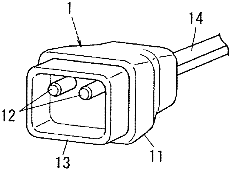
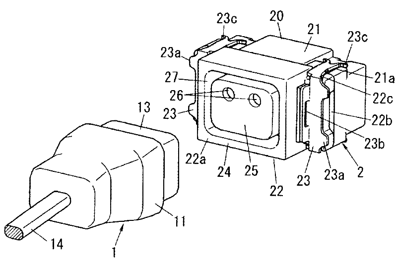
[0046] will refer to Figure 1A to Figure 2C A first embodiment of the present invention is described. The plug 1 according to this embodiment is, for example, detachably connected to a DC outlet 2 buried in a building surface such as a wall. Such as Figure 1B As shown, a plug connector for DC power is composed of a plug 1 and a DC socket 2 connected to the plug 1 to supply DC power thereto. Unless otherwise described, the upward, downward, left and right directions of the plug 1 are based on Figure 1A And limited. Figure 1A The surface of the paper in indicates the front side of plug 1.
[0047] Such as Figure 1A and Figure 1B Explain that the plug 1 includes a plug body 11 having a horizontally elongated rectangular hexahedron shape and a size that can be held by a user. The plug body 11 is made of thermoplastic synthetic resin. Two round bar-shaped plug pins 12 to which power from the DC outlet 2 is supplied protrude from the front surface (the surface facing th...
no. 2 example
[0070] will refer to Figure 3A to Figure 3F A second embodiment of the present invention is described. The plug 1 of this embodiment is used for a plurality of supply voltages, and the shape of the surrounding wall 13 is partially changed depending on the kind of supply voltage. Except for the shape of the surrounding wall 13, the second embodiment is the same as the first embodiment. Therefore, the same components are designated by the same reference numerals, and redundant descriptions thereof will be omitted.
[0071] The plug 1 of this embodiment is used for four DC supply voltages (eg approximately 6V, 12V, 24V and 48V). Therefore, the shape of the surrounding wall 13 is partially changed depending on the kind of supply voltage.
[0072] Figure 3A to Figure 3D Front views of plugs 1 for 6V, 12V, 24V and 48V respectively are provided. In the plug 1 for 24V, the surrounding wall 13 has a substantially quadrangular shape viewed in the plug insertion direction (from th...
no. 3 example
[0082] will see Figure 5A to Figure 6EA third embodiment of the present invention is described. In the second embodiment, the shape of the corner of the surrounding wall 13 is changed depending on the kind of supply voltage. However, in the third embodiment, depending on the kind of the power supply circuit serving as the power supply source, the shape of the surrounding wall 13 is partially changed by forming an extension part protruding from the surface of the surrounding wall 13 . Except for the shape of the surrounding wall 13, the third embodiment is the same as the second embodiment. Therefore, the same components are designated by the same reference numerals, and redundant descriptions thereof will be omitted.
[0083] Power supply circuits (for example, SELV circuits, ELV circuits, FELV circuits, and the like) serving as power supply sources are standardized in IEC standards. In the plug 1 for the SELV circuit, the extension portion 15 protrudes inwardly from the l...
PUM
 Abstract
Description
Claims
Application Information
 - R&D
- Intellectual Property
- Life Sciences
- Materials
- Tech Scout
- Unparalleled Data Quality
- Higher Quality Content
- 60% Fewer Hallucinations
Browse by: Latest US Patents, China's latest patents, Technical Efficacy Thesaurus, Application Domain, Technology Topic, Popular Technical Reports.
© 2025 PatSnap. All rights reserved.Legal|Privacy policy|Modern Slavery Act Transparency Statement|Sitemap|About US| Contact US: help@patsnap.com