
Burner system and method for damping such a burner system

A burner and combustion chamber technology, applied in combustion methods, combustion chambers, combustion equipment, etc., can solve problems such as flame temperature increasing NOx emissions, etc.

Inactive Publication Date: 2012-05-23
SIEMENS AG
View PDF8 Cites 3 Cited by
  • Summary
  • Abstract
  • Description
  • Claims
  • Application Information

AI Technical Summary

Problems solved by technology

This increases the flame temperature and increases NOx emissions

Method used


Image

  • Burner system and method for damping such a burner system
  • Burner system and method for damping such a burner system
  • Burner system and method for damping such a burner system

Examples


Embodiment Construction

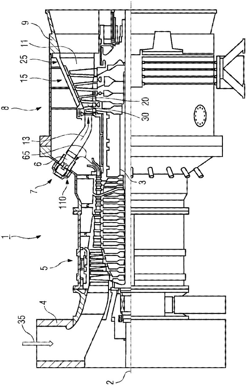
[0023] figure 1 The gas turbine 1 is shown by way of example in a partial longitudinal section.

[0024] The gas turbine 1 has internally a rotor 3 with a shaft mounted in rotation about an axis of rotation 2 , which is also referred to as a turbine rotor.

[0025] The sequence along the rotor 3 is an intake casing 4, a compressor 5, a torus-type combustor 6, for example comprising a plurality of coaxially arranged burners 7, especially a single-tube combustor or an annular combustor, a turbine 8 and an exhaust gas Receiver 9.

[0026] The combustion chamber 6 is connected to, for example, an annular hot gas channel 11 . There, for example, four turbine stages 12 connected in series form the turbine 8 .

[0027] Each turbine stage 12 consists, for example, of two blade rings. Viewed along the flow direction of the working medium 13 , the vane set 25 formed by the working vanes 20 is arranged behind the guide vane set 15 in the hot gas channel 11 .

[0028] During operatio...


PUM


Abstract

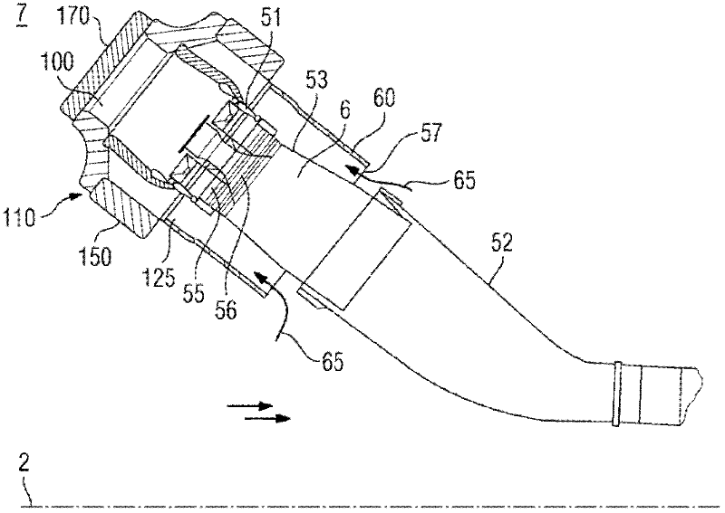
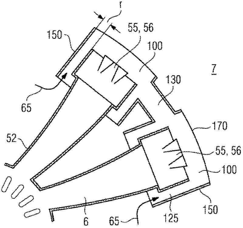
The invention relates to a burner system comprising at least two adjacent burners (7) that are separate from each other, each of which has at least one combustion chamber (6) and a head end (51), wherein the latter comprises at least a fuel injection (55) and a fuel-air premix (56), wherein each burner (7) has a cap (110) with a cap side (150) and a cap upper side (170), wherein at least the cap upper side (170) is arranged ahead of the head end (51), seen in the direction of flow, and so a burner plenum (100) is formed between the cap upper side (170) and the head end (51), wherein the at least two burner plenums (100) have an acoustic connection. The invention also relates to a method for damping such a burner system.

Description

technical field [0001] The present invention relates to a burner system comprising at least two adjacent burners independent of each other, wherein each burner has at least one combustion chamber and a top end including at least one fuel injection device and a fuel-air preheater Mixing device, each burner has a head cover including a head cover side and a head cover upper side, wherein at least the head cover upper side is arranged in front of the top end as viewed in the flow direction, thereby forming a burner between the head cover upper side and the top end air cavity. Background technique [0002] In combustion systems such as gas turbines, aero engines, rocket engines and heating equipment, thermoacoustic induced combustion oscillations can result. They are formed by the interaction of a combustion flame and an exotherm with associated sound pressure fluctuations. By means of acoustic excitation, the flame position, the flame front or the composition of the mixture c...

Claims


Application Information

Patent Timeline
Patent Type & Authority Applications(China)
IPC IPC(8): F23R3/28F23R3/46F23R3/54F23M99/00
CPCF23R3/54F23R3/286F23R3/46F23R2900/00014F23M99/005F23M20/005
Inventor S.贝斯克
Owner SIEMENS AG
Learn More