Fuel injection valve for internal combustion engines

A technology of fuel injection valve and internal combustion engine, which is applied in the direction of fuel injection device, special fuel injection device, charging system, etc., can solve problems such as cost-effective manufacturing, and achieve the effect of stable flow decomposition

Active Publication Date: 2012-05-23
ROBERT BOSCH GMBH
View PDF5 Cites 0 Cited by
  • Summary
  • Abstract
  • Description
  • Claims
  • Application Information

AI Technical Summary

Problems solved by technology

However, the throttle valve proposed in DE 10 2007 032 741 which is formed by a collar on the valve needle has the disadvantage that the sharp-edged throttle described there is only expensive to produce.

Method used


Image

  • Fuel injection valve for internal combustion engines
  • Fuel injection valve for internal combustion engines
  • Fuel injection valve for internal combustion engines

Examples


Embodiment Construction

[0018] exist figure 1 The fuel injection valve according to the invention is shown in longitudinal section, wherein only the part of the injection valve which is facing the combustion chamber in the installed position of the internal combustion engine is shown. The fuel injector 1 has a valve body 2 in which a pressure chamber 5 is formed in the form of a bore. The pressure chamber 5 is delimited on the combustion chamber side by an essentially conical valve seat 9 from which a plurality of injection openings 7 emerge. Arranged in the pressure chamber 5 is a longitudinally displaceable valve needle 3 which is embodied rotationally symmetrically with respect to the longitudinal axis of the pressure chamber 5 . The valve needle 3 is guided in the guide section 103 in the pressure chamber 5 , wherein a fuel flow is ensured through milled portions 14 formed on the outside of the guide section 103 and past the guide section 103 . On its end facing the valve seat, the valve needle...


PUM


Abstract

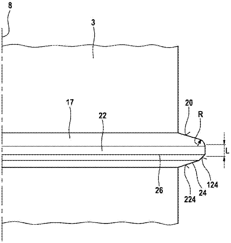
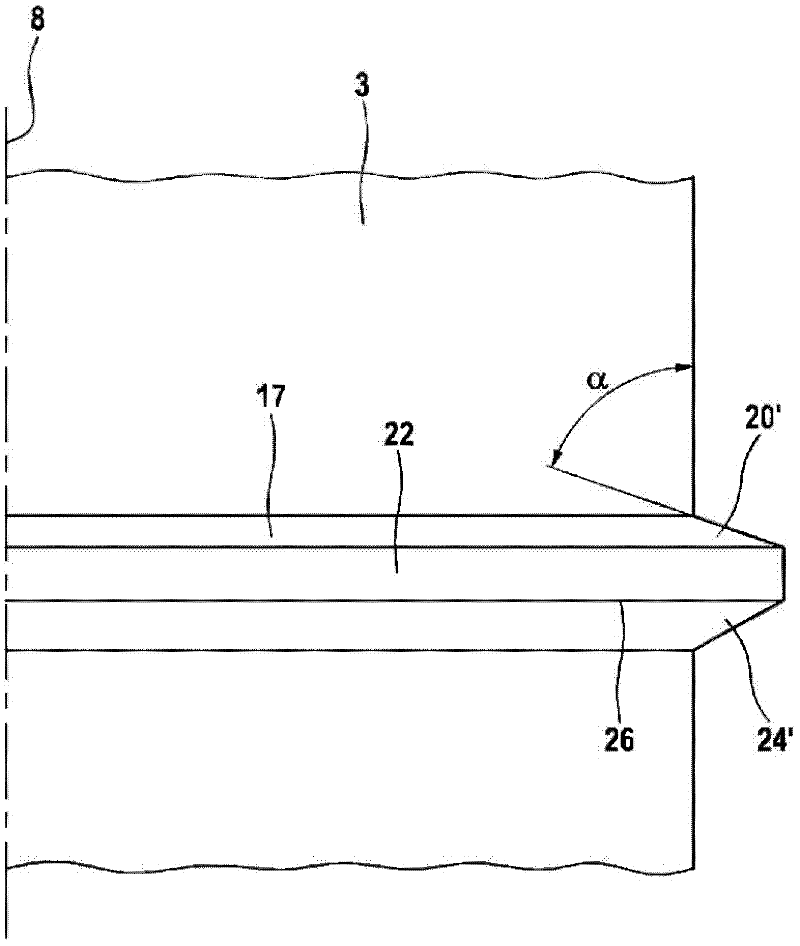
Fuel injection valve for internal combustion engines having a valve body (1), in which a pressure chamber (5) is formed, in which a valve needle (3) is arranged such that it can be displaced longitudinally, which valve needle (3) interacts by way of a valve sealing surface (11) which is formed on the valve needle (3) with a valve seat (9) which delimits the pressure chamber (5). As a result of the interaction of the valve needle (3) with the valve seat (9), a fuel flow to at least one injection opening (7) is made possible or interrupted, wherein the fuel flow flows through between the valve needle (3) and the wall of the pressure chamber (5) to the injection openings (7). A collar (17) is formed on the valve needle (3), with the result that a gap throttle (15) is formed between the wall of the pressure chamber (5) and the collar (17), wherein the collar (17) has an inlet-side surface (20) and an outlet-side surface (24), wherein the inlet-side surface (20) is of rounded or conical configuration.

Description

technical field [0001] The invention relates to a fuel injection valve for an internal combustion engine, such as preferably for direct injection of fuel into the combustion chamber of a fast-running, self-igniting internal combustion engine. Background technique [0002] Fuel injection valves for injecting fuel directly at high pressure into the combustion chamber of the internal combustion engine operate at a constant high pressure. Injection pressures in excess of 2000 bar have been achieved in part today. In this case, the fuel pressure is generated by a high-pressure pump which delivers the compressed fuel into a high-pressure accumulator of the so-called common rail. In most cases, a plurality of injectors with moving valve needles are fed by the common rail, opened in a controlled manner by means of injection orifices by electronically controlled valves, and control such that fuel is injected into the combustion chamber at the desired time and in the desired dose . ...

Claims


Application Information

Patent Timeline
Patent Type & Authority Applications(China)
IPC IPC(8): F02M61/16F02M61/20
CPCF02M61/16F02M2200/28F02M61/205
Inventor M·布格尔H-C·马盖尔
Owner ROBERT BOSCH GMBH
Why Eureka
Try Eureka