Robot, robot control device, and control method
A technology of robots and robot arms, applied in the field of robots, can solve problems such as unstable control and robot failure, and achieve the effect of preventing the moving area of joints from being crossed
- Summary
- Abstract
- Description
- Claims
- Application Information
AI Technical Summary
Problems solved by technology
Method used
Image
Examples
no. 1 approach
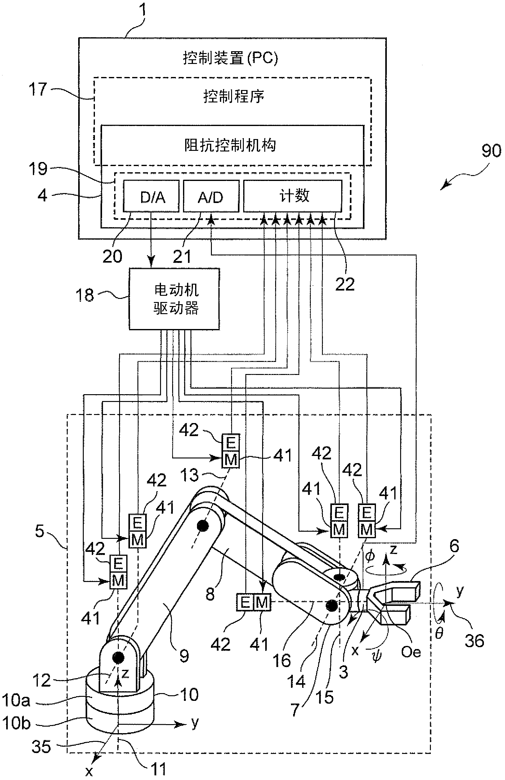
[0087] figure 1 It is a figure which shows the structure of the robot 90 which concerns on 1st Embodiment of this invention. The robot 90 includes a multi-joint robot arm 5 and a control device 1 for controlling the operation of the multi-joint robot arm 5 .
[0088] In terms of hardware, the control device 1 is generally constituted by a personal computer. In addition, the portion of the impedance control mechanism (impedance control unit) 4 other than the input / output IF 19 is realized by software as a control program 17 executed by a personal computer.
[0089] The input / output IF 19 is composed of a D / A board 20, an A / D board 21, and a counter board 22 connected to an expansion slot such as a PCI bus of a personal computer.
[0090] The control device 1 functions by executing the control program 17 for controlling the operation of the articulated robot arm 5 of the robot 90 . The joint angle information output from each encoder 42 of each joint 11, 12, 13, 14, 15, 16 of...
no. 2 approach
[0273] The basic configuration and figure 1 and figure 2 The situation of the first embodiment shown is the same, so the description of the common parts will be omitted, and only the different parts will be described in detail below.
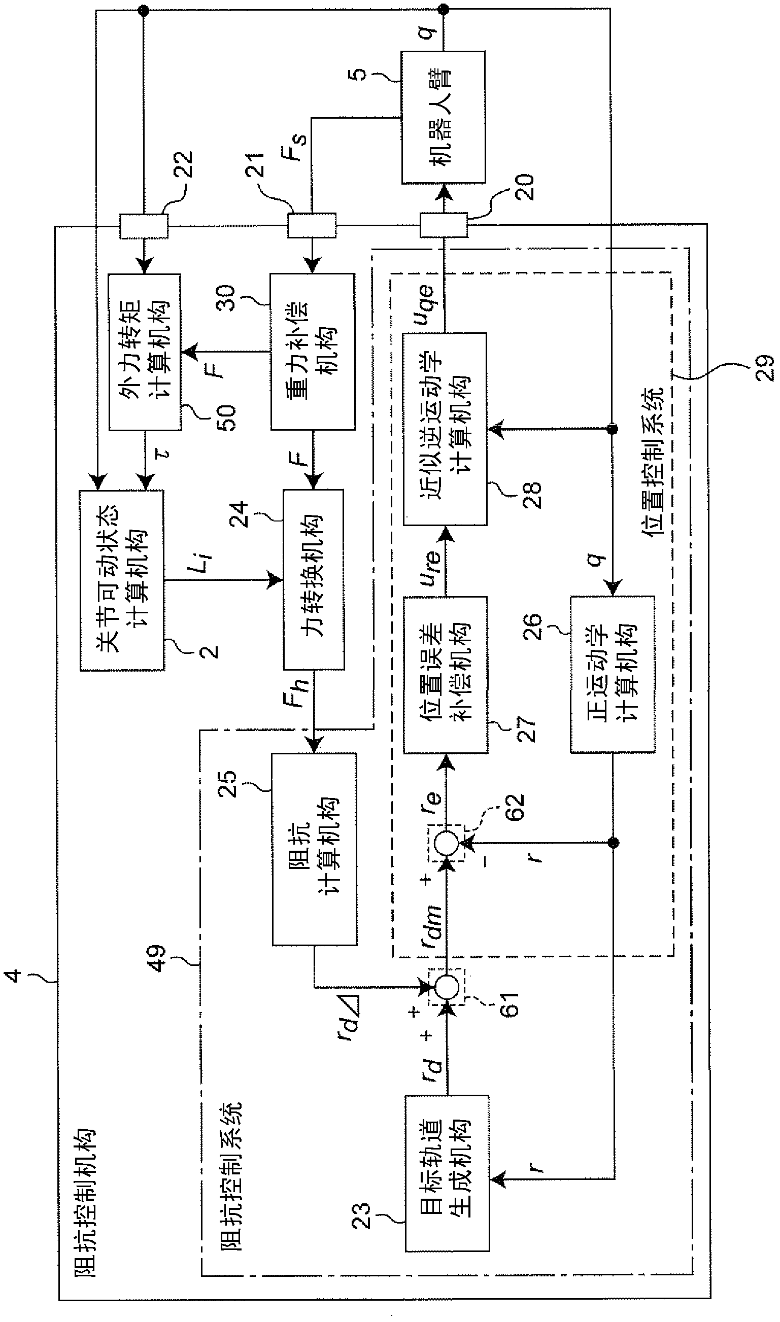
[0274] like Figure 7 As shown, in the second embodiment, with the usual impedance control mechanism 43 (namely, the impedance calculation mechanism 25, the target trajectory generation mechanism 23, the forward kinematics calculation mechanism 26, the position error compensation mechanism 27, the approximate inverse kinematics calculation mechanism 28. The first calculation part 61, the second calculation part 62) The independent force input control mechanism 34 is equipped with the joint movable state calculation mechanism 2 and the force conversion mechanism 24, forming the same as the original control device (first control device) The composition of 1B communication.
[0275] Figure 8 The overall configuration of the robot 90B of the s...
no. 3 approach
[0281] The basic configuration and figure 1 and figure 2 The case of the first embodiment shown is the same, the description of the common parts will be omitted, and only the different parts will be described in detail below.
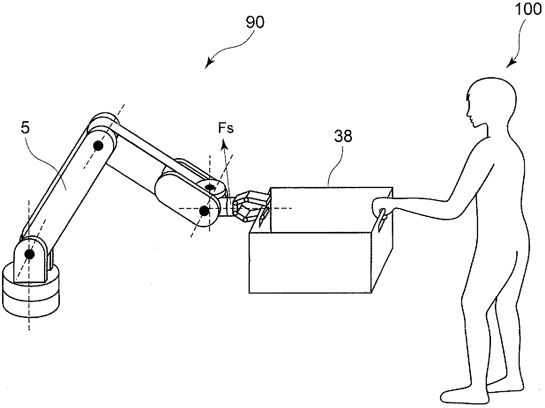
[0282] Figure 9 is a block diagram showing the configuration of the impedance control mechanism of the robot 90C according to the third embodiment of the present invention, Figure 10 It is a figure explaining the cooperative conveyance operation of the robot 90C and the person 100.
[0283] like Figure 10 As shown, the robot 90C of the third embodiment has an operation handle 40 fixed to the wrist 7 via the force sensor 3 , and the human 100 can directly hold the operation handle 40 and apply force to operate the robot 90C. A force sensor 3 is arranged between the operation handle 40 and the robot arm 5 , and the force when the human 100 operates it can be detected by the force sensor 3 .
[0284] In addition, the operation handle 40 is provide...
PUM
 Abstract
Description
Claims
Application Information
 - R&D
- Intellectual Property
- Life Sciences
- Materials
- Tech Scout
- Unparalleled Data Quality
- Higher Quality Content
- 60% Fewer Hallucinations
Browse by: Latest US Patents, China's latest patents, Technical Efficacy Thesaurus, Application Domain, Technology Topic, Popular Technical Reports.
© 2025 PatSnap. All rights reserved.Legal|Privacy policy|Modern Slavery Act Transparency Statement|Sitemap|About US| Contact US: help@patsnap.com


