Gas-insulated switch

A gas-insulated switch, gas technology, applied in electrical switches, high-voltage/high-current switches, electrical components, etc., can solve problems such as spending a lot of labor and time on permanent magnets, not suitable for effectively rotating and driving arcs, and hindering the miniaturization of devices. , to achieve the effect of improving truncation performance, low operating force and stable truncation performance

Active Publication Date: 2011-05-11
JAPAN AE POWER SYST
View PDF2 Cites 0 Cited by
  • Summary
  • Abstract
  • Description
  • Claims
  • Application Information

AI Technical Summary

Problems solved by technology

For example, in the case of the arc drive method using permanent magnets, the design must take into account the permanent magnet aging due to the temperature change due to the current flowing during operation, and it takes a lot of labor and time to evaluate the permanent magnet aging degree
In addition, in the case of cutting off the alternating current, since the rotation direction of the arc will be reversed every half cycle, it is not suitable for effectively rotating and driving the arc in principle.
[0007] In addition, in the case of an arc-driven known gas-insulated switch using an arc-driving coil, it is necessary to arrange the arc-driving coil near the arc-generating part, and the current does not flow through the arc-driving coil in a stable operation state. Therefore, the structure of this part is complicated and the outer diameter is also large, which hinders the miniaturization of the device

Method used


Image

  • Gas-insulated switch
  • Gas-insulated switch
  • Gas-insulated switch

Examples


Embodiment Construction

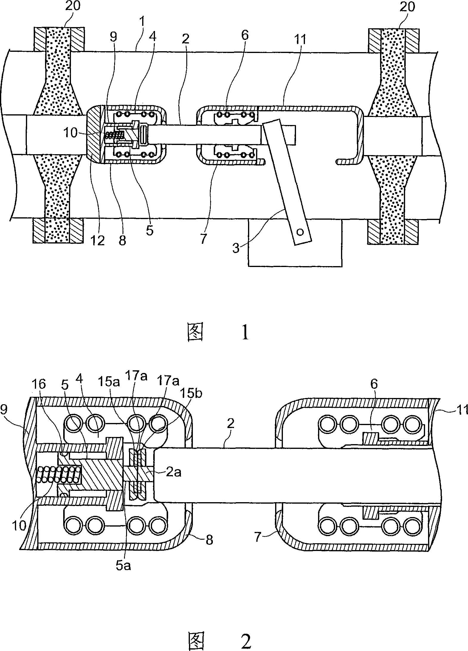
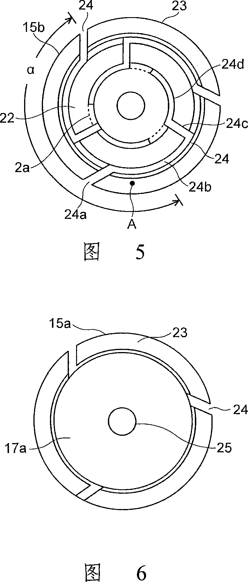
[0029] Next, first, a gas insulated switch as an example of the present invention will be described with reference to FIGS. 1 , 2 and 5 .

[0030] The electrode closed state of the gas insulated switch of the present invention is shown in the sectional view of FIG. 1 . In the airtight container 1, a gas region is formed by an insulating gasket 20. In this gas region, as an insulating gas, SF 6 Negative gas such as gas, dry air, nitrogen, carbon dioxide, SF containing negative gas 6 / N 2 Mixed gas, N without negative gas 2 / O 2 mixed gas etc.

[0031] Among the conductors embedded in the central part of the insulating gasket 20, the movable side and the fixed side high voltage conductors 11, 12 are respectively supported and fixed in a state of being electrically insulated from the airtight container 1, and are separated from each other by a predetermined insulation distance. On the opposing parts of the high voltage conductors 11, 12, seals 7, 8 for electric field relaxat...


PUM


Abstract

The invention provides a gas insulated switchgear, capable of preventing the diameter from enlarging in simple structure and rotating the arc with good efficiency and realizing the downsizing and light-weighting in low operating physical force. The opposite side insulating parts (17a) are set at the opposite surface of the non-contact depressed part (22) in the spiral electrodes (15a,15b), in addition a rear-face side insulator (17b) having an equivalent or greater diameter is arranged at a rear face side of the spiral electrodes (15a, 15b). Thus even thought part of the periphery of the arc (26) leaves the arc moving part (23) and protrudes from the non-contact depressed part (22) side or the arc moving part (23), the insulating parts (17a,17b) can still prevent part of the current flowing through the arc (26) from spanning the groove (26b) and flowing through the non-contact depressed part (22) or flowing through the rear-face side of the spiral electrodes (15a,15b), therefore the action to the arc (26) can be stably performed for a long time, depending on the total shape of the groove and the electromagnetic force of the current.

Description

technical field [0001] The present invention relates to a gas insulated switch, in particular to a gas insulated switch having arc contacts which are in electrical contact with each other when the electrodes are closed and which cause an arc to ignite when the electrodes are disconnected. Background technique [0002] Generally, in a gas insulated switch, an arc contact is provided in order to prevent the arc generated when the passing electrode is disconnected from damaging the energization contact or the seal. That is, a known gas insulated switch has a structure in which a fixed-side conductor and a movable-side conductor are arranged at a predetermined opposing distance, an arc contact is provided on the fixed-side conductor, and a movable member is provided on the movable-side conductor. , An elastic contact part is provided at the front end of the arc contact or the movable part, and the movable part is electrically connected to the arc contact through the elastic cont...

Claims


Application Information

Patent Timeline
Patent Type & Authority Patents(China)
IPC IPC(8): H01H33/16
Inventor 六户敏昭八木桥义丰大森庄司山本直幸
Owner JAPAN AE POWER SYST
Why Eureka
Try Eureka