
Protective cap, and electric tool with such a protective cap

A technology of electric tools and protective covers, applied in the field of protective covers

Inactive Publication Date: 2009-11-18
AEG ELECTRIC TOOLS
View PDF3 Cites 3 Cited by
  • Summary
  • Abstract
  • Description
  • Claims
  • Application Information

AI Technical Summary

Problems solved by technology

This requirement cannot be fulfilled by a stop cam on the retaining ring (formed by a spring-elastic plate)

Method used


Image

  • Protective cap, and electric tool with such a protective cap
  • Protective cap, and electric tool with such a protective cap

Examples


Embodiment Construction

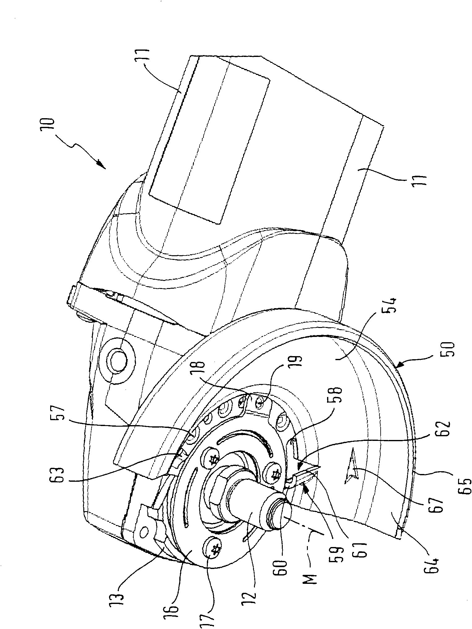
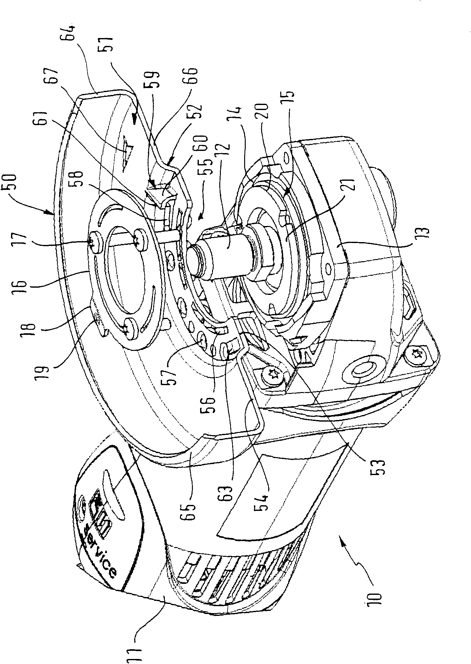
[0017] exist figure 1 and 2 The angle grinder shown in is an example of a power tool to which the invention can be applied. The angle grinder comprises a housing 11 in which a drive unit, which cannot be seen in the figures, is accommodated. A drive spindle 12 is rotated (here counterclockwise) by the drive, on which a grinding disc (not shown) can be fixed. exist figure 1 The central axis M of the drive spindle 12 is shown in . The drive spindle 12 is mounted in a housing 11 . The portion supporting the drive spindle is covered by an end shield 13 connected to the housing 11 . Formed in the end shield 13 is an annular groove 14 which is open in the front region 15 over an angular region of approximately 160°.

[0018] Furthermore, a retaining ring 16 formed from an elastic material, in particular a spring plate, is fastened in the end cap 13 by means of a screw connection 17 . The retaining ring 16 has, as a counter element, a projection 18 which is bent slightly downwa...


PUM


Abstract

The present invention relates to a protective cowl, which can be fixed on an electric tool, especially an angle grinder in manner of being capable of swinging around a drive shaft (12) of the electrictool (10) to different positions in defined angle range. The protective cowl comprises: a body having a sector wall part (51); a plurality of holding elements (57) arranged on the wall part (51) along partial arc homocentric with the sector section, the holding elements being capable of jointing with corresponding elements (18) relative to the electric tool (10) to hold the protective cowl at selected operation position; in order to limit the swing movement along the circle direction in at least one of end zones of partial arc, at least a block (59) extending in axial direction is provided, which may move towards the corresponding elements (18), and the block (59) has a leg (61) extending to the partial arc section so as to form a bag shaped part (62), such that the corresponding elements(18) can be moved into the bag shaped part (62).

Description

technical field [0001] The invention relates to a protective cover for a power tool, in particular an angle grinder, and to a power tool with such a protective cover. Background technique [0002] An angle grinder is known from DE 44 23 889 C1, to which a protective hood is detachably fastened. After fastening, the protective hood can be pivoted into different operating positions within a defined angular range around the drive spindle of the power tool, on which the tool (here the grinding disc) is fastened. In order to keep the guard in a desired angular position, on a sector-shaped wall extending parallel to the end shield of the power tool, along a partial arc coaxial with the drive spindle, a plurality of Evenly distributed depressions in the partial arc. In addition, a retaining ring made of a spring-elastic sheet metal (spring steel) is fastened to the end shield, the retaining ring having a snap-in cam that rests on the sector-shaped wall. The snap-in lug has a pro...

Claims


Application Information

Patent Timeline
IPC IPC(8): B25F5/00B24B55/05
CPCB24B23/028B24B55/052
Inventor 赫尔穆特·施密特
Owner AEG ELECTRIC TOOLS
Learn More