Method and device for preventing slip of work piece

A workpiece and anti-slip technology, which is applied in the control of workpiece feed movement, machine tools designed for grinding workpiece rotating surfaces, grinding workpiece supports, etc., can solve the problems of undetectable abnormal rotation, etc., and achieve anti-slip and high-precision measurement Effect

Inactive Publication Date: 2012-05-23
JTEKT CORP
View PDF11 Cites 7 Cited by
  • Summary
  • Abstract
  • Description
  • Claims
  • Application Information

AI Technical Summary

Problems solved by technology

[0008] Since the devices described in Patent Document 2 and Patent Document 3 detect the abnormal rotation of the workpiece by using the non-circular part of the workpiece or the non-circular component mounted on the rolling center, it is useful in camshafts, crankshafts, etc. Abnormal rotation can be detected in a workpiece with a non-circular portion, but in a cylindrical workpiece without a non-circular portion, abnormal rotation cannot be detected unless a special center such as that described in Patent Document 3 is provided. question

Method used


Image

  • Method and device for preventing slip of work piece
  • Method and device for preventing slip of work piece
  • Method and device for preventing slip of work piece

Examples


Embodiment Construction

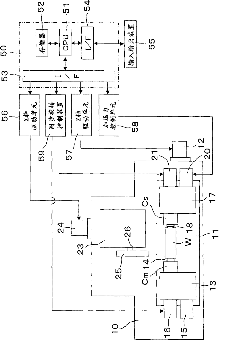
[0049] Embodiments of the present invention will be described below based on the drawings. like figure 1 As shown, on the bed 10 of the grinding machine, the workbench 11 is guided and supported by the Z-axis servo motor 12 and can move along the Z-axis direction ( figure 1 left and right directions) to move. The table 11 is provided with a headstock 13 rotatably supporting the main spindle Cm, and a center 14 supporting one end of the workpiece W is attached to the end of the main spindle Cm. The main spindle Cm is formed to move forward and backward by a predetermined amount in the axial direction by the forward and backward drive device 15 , and is driven to rotate by the main servo motor 16 .

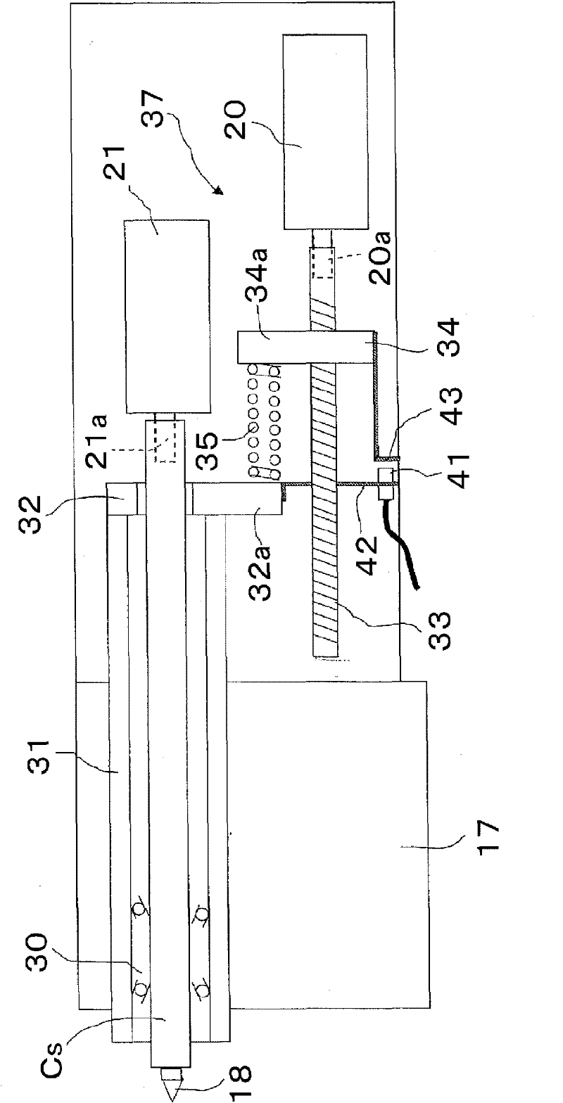
[0050] On the table 11, a tailstock 17 is provided at a position opposite to the headstock 13. On the tailstock 17, the driven spindle Cs is supported coaxially with the driving spindle Cm so that the driven spindle Cs The main shaft Cs is rotatable, and a center 18 supporting th...


PUM


Abstract

A master servo motor (16) and a slave servo motor (21) that synchronously drive for rotation a master main spindle Cm provided with a center (14) that supports one end of a work piece W and a slave main spindle Cs provided with a center (18) that supports the other end of the work piece are included. Before grinding, a slip detection cycle that detects a limit current value (A1) for the servo motors, at which the work piece and the centers slip, is executed and, during grinding, a grinding condition is changed to prevent a slip between the work piece and the centers in advance at the time when any one of current values of the servo motors has reached a slip threshold value (A2) set on the basis of the limit current value.

Description

technical field [0001] The invention relates to a workpiece anti-slip method and device in a grinding machine for grinding the workpiece by driving both ends of the workpiece with the friction force of a center so that the two ends of the workpiece rotate synchronously. Background technique [0002] For example, a grinding machine described in Patent Document 1 is known. For a workpiece supported at both ends by a center, by increasing the pressing force of the center, the friction force of the center is used to drive both ends of the workpiece so that the two ends of the workpiece rotate synchronously. Thereby grinding the workpiece. In the grinding machine of the above structure, since it is not necessary to clamp the end of the workpiece or to install a driver, it is possible to perform grinding over the entire length without changing the way of clamping the cylindrical workpiece, for example, and without Drivers and the like corresponding to various workpieces with diff...

Claims


Application Information

Patent Timeline
Patent Type & Authority Applications(China)
IPC IPC(8): B24B49/16B24B5/02B24B41/06B24B49/10
CPCB24B49/10B24B5/045B24B49/16B24B41/062Y10T409/300896Y10T409/305656Y10T409/307336
Inventor 牧内明
Owner JTEKT CORP
Why Eureka
Try Eureka