Built-in testing method for delay of trigger and circuit
A technology with built-in test circuits and triggers, which is applied in the measurement of electricity, measurement of electrical variables, and digital circuit testing. System final frequency and other issues
- Summary
- Abstract
- Description
- Claims
- Application Information
AI Technical Summary
Problems solved by technology
Method used
Image


Examples
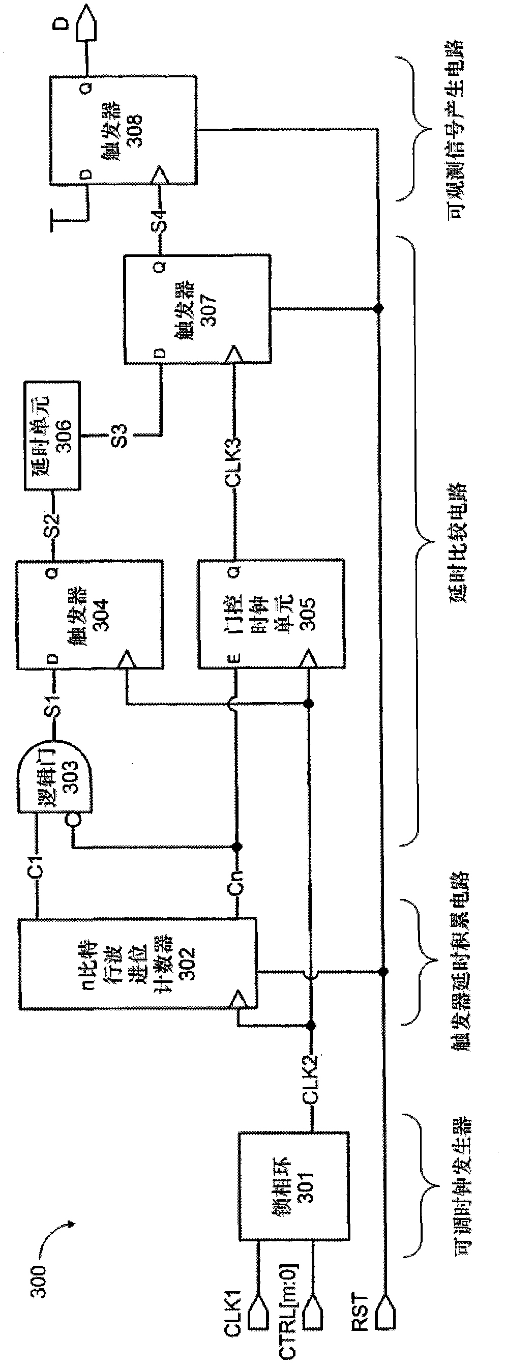
Embodiment 300
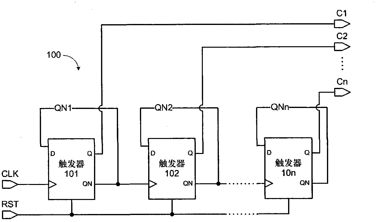
[0023] figure 1 A circuit embodiment using a ripple carry counter 100 to accumulate the delay of the flip-flop under test is shown. The QN output terminal of the flip-flop 101 is connected to its own D input terminal by means of feedback, and QN is used as the clock input terminal of the next-stage flip-flop 102 . By analogy, n identical flip-flops to be tested are cascaded to form a ripple carry counter.
[0024] figure 2 The working waveform diagram of the ripple carry counter 100 is shown. When the reset signal RST turns to the active state 211, the output terminals QN of the flip-flops under test 101 to 10n are reset to high level, and the output terminal Q is reset to low level. At this time, the outputs C1 to Cn of the ripple carry counter 100 are all low level, that is, decimal 0. When the reset signal RST is turned into an invalid state 212, driven by the rising edge 201 of the clock CLK, the flip-flop 101 to be tested samples QN1 (high level), so that C1 turns to...
PUM
 Abstract
Description
Claims
Application Information
 - Generate Ideas
- Intellectual Property
- Life Sciences
- Materials
- Tech Scout
- Unparalleled Data Quality
- Higher Quality Content
- 60% Fewer Hallucinations
Browse by: Latest US Patents, China's latest patents, Technical Efficacy Thesaurus, Application Domain, Technology Topic, Popular Technical Reports.
© 2025 PatSnap. All rights reserved.Legal|Privacy policy|Modern Slavery Act Transparency Statement|Sitemap|About US| Contact US: help@patsnap.com