
Light emitting module

A technology for light-emitting modules and light-emitting devices, which can be applied to light sources, semiconductor devices of light-emitting elements, light source fixing, etc., and can solve problems such as product reliability deterioration.

Active Publication Date: 2012-05-16
LG INNOTEK CO LTD
View PDF5 Cites 9 Cited by
  • Summary
  • Abstract
  • Description
  • Claims
  • Application Information

AI Technical Summary

Problems solved by technology

Accordingly, the reliability of the product will deteriorate

Method used


Image

  • Light emitting module
  • Light emitting module
  • Light emitting module

Examples


Embodiment Construction

[0033] Hereinafter, the embodiments will be described in detail with reference to the accompanying drawings so that those skilled in the art can easily utilize the embodiments. However, the embodiments may have various modifications. In the drawings, parts irrelevant to the description are omitted in order to clarify the embodiments. In the following description, similar reference numerals will be assigned to similar components.

[0034] In the following description, when a predetermined part "includes" a predetermined component, the predetermined part does not exclude other components but may further include other components if there is a specific contrary description.

[0035] The thickness and size of each layer shown in the drawings may be exaggerated, omitted, or schematically drawn for convenience or clarity. In addition, the size of elements does not utterly reflect an actual size.

[0036] In the description of the embodiments, it will be understood that when a laye...


PUM


Abstract

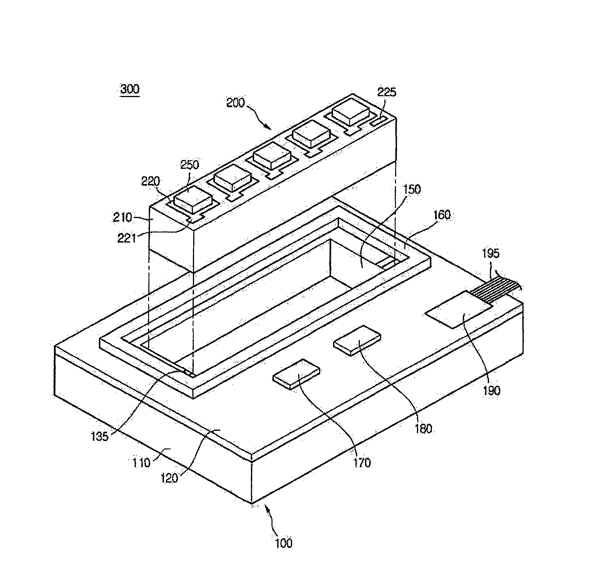
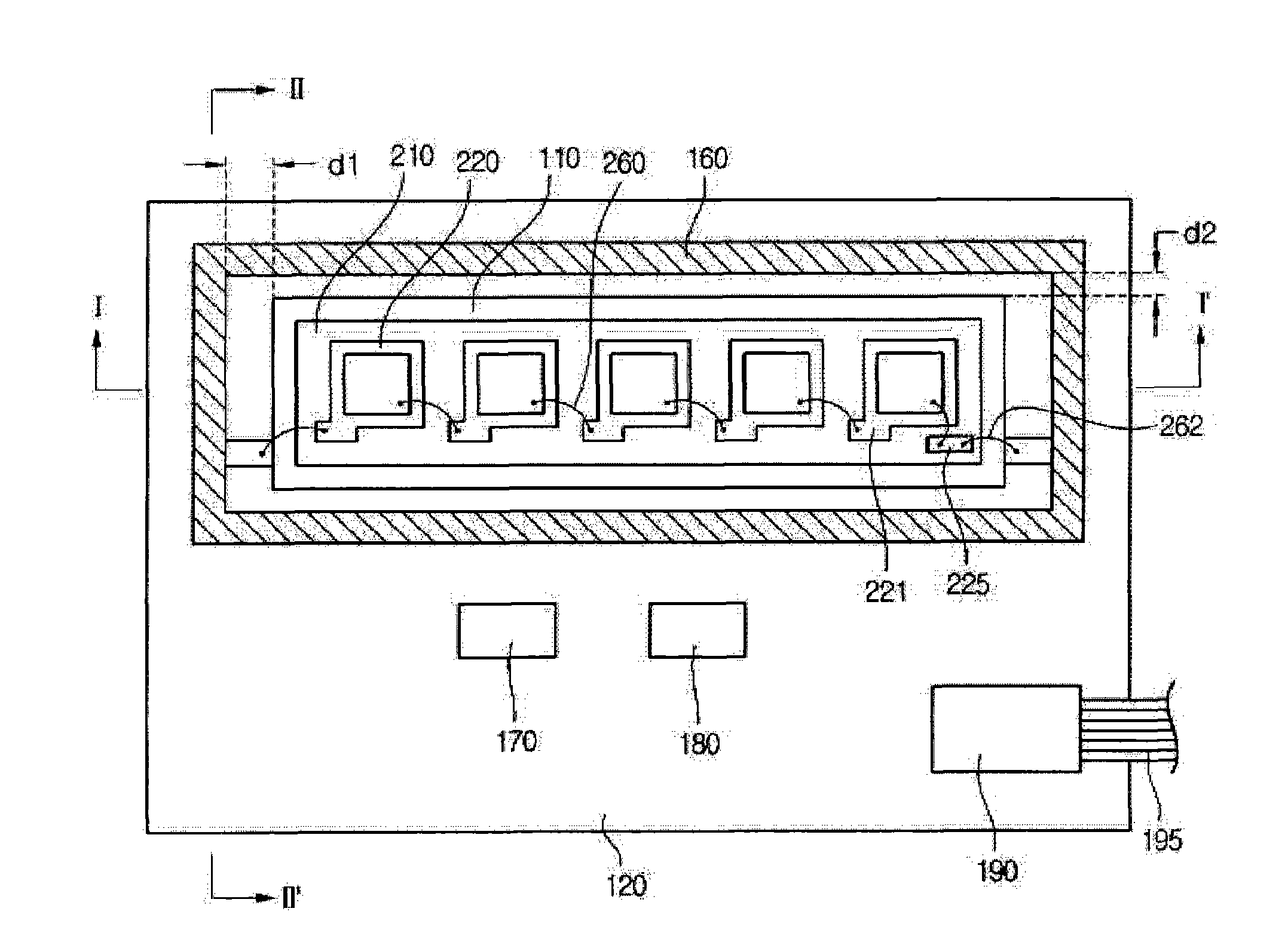
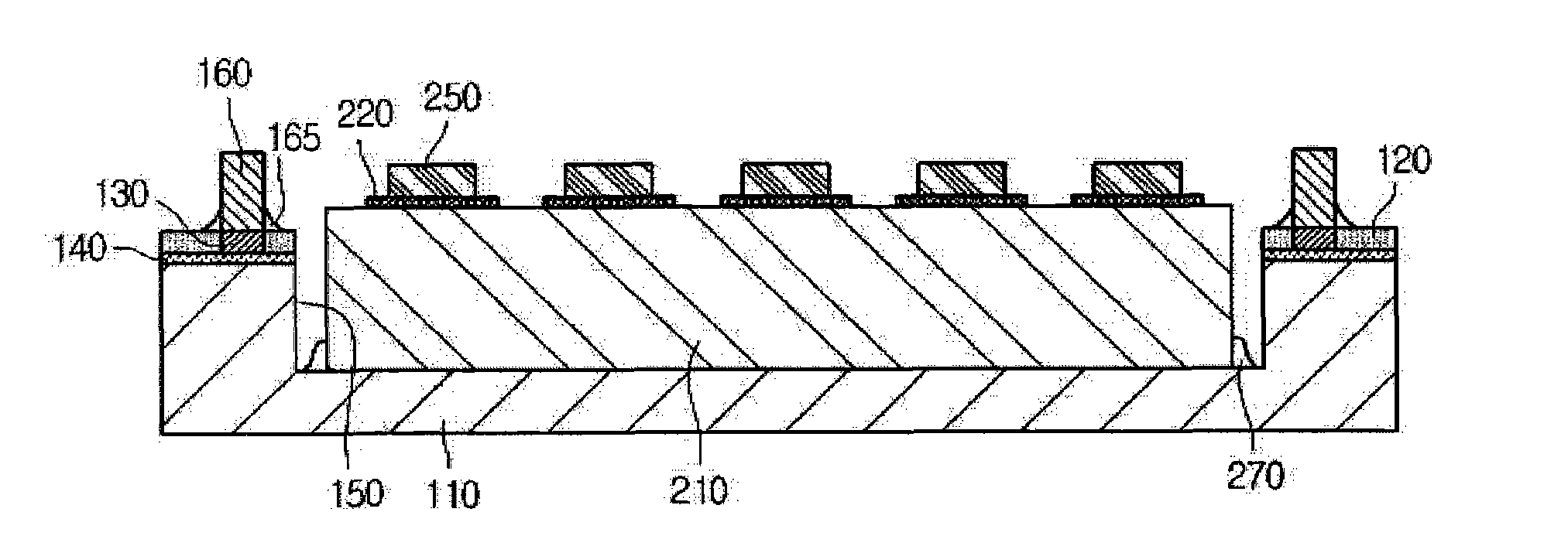
Disclosed is a light emitting module capable of representing improved heat radiation and improved light collection. there is provided a light emitting module. The light emitting module includes a metallic circuit board formed therein with a cavity, and a light emitting device package including a nitride insulating substrate attached in the cavity of the metallic circuit board, at least one pad part on the nitride insulating substrate, and at least one light emitting device attached on the pad part.

Description

technical field [0001] Embodiments relate to a light emitting module. Background technique [0002] Generally, a circuit board is obtained by forming a circuit pattern by using a conductive material such as copper on an electrically insulating substrate, and refers to a substrate before heat emitting devices related to electronic components are mounted thereon. The circuit board is provided thereon with semiconductor devices and heat-emitting devices such as LEDs (Light Emitting Diodes). [0003] In particular, circuit boards having LEDs mounted thereon have been developed for headlights of vehicles, so that heat resistance and heat transfer characteristics have been required. [0004] However, devices such as LEDs emit a considerable amount of heat. If the circuit board with the LEDs does not handle the heat, the temperature of the circuit board equipped with the heat emitting device increases so that the heat emitting device may not operate or operate incorrectly. Accor...

Claims


Application Information

Patent Timeline
Patent Type & Authority Applications(China)
IPC IPC(8): H01L25/075H01L33/48H01L33/62H01L33/64
CPCF21S48/321F21S48/115H01L33/641H05K2201/09745H05K2201/10106H05K3/284F21Y2103/003H01L33/642H05K1/0203H01L25/167H05K1/05F21V19/003H01L33/52F21S48/1109F21K9/00H01L2224/48091H01L33/58H05K2201/2018F21Y2101/02F21Y2103/10F21Y2115/10F21S41/151F21S41/192F21S45/47F21S45/49H01L33/54H01L2924/00014
Inventor 赵允旻
Owner LG INNOTEK CO LTD
Learn More