
Gas tank header part and machining method thereof as well as thermal expansion valve using part

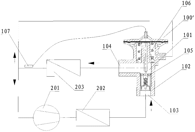
A thermal expansion valve and gas box head technology, applied in the field of thermal expansion valves, can solve the problems of unguaranteed welding quality, small welding contact surface, high processability requirements, etc., to improve welding reliability, reduce thermal influence, and increase area Effect

Inactive Publication Date: 2012-05-16
ZHEJIANG SANHUA INTELLIGENT CONTROLS CO LTD
View PDF10 Cites 3 Cited by
  • Summary
  • Abstract
  • Description
  • Claims
  • Application Information

AI Technical Summary

Problems solved by technology

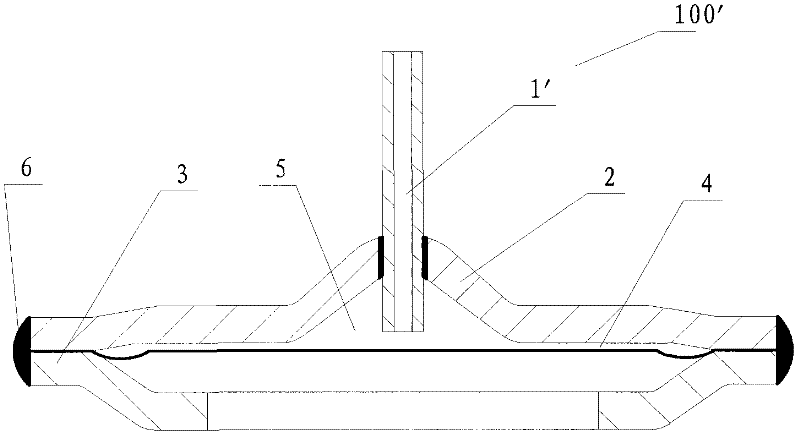
The connection method between the capillary and the gas box cover in the prior art is to insert the capillary directly into the introduction hole of the gas box cover, and weld by adding high-temperature fusion materials. Since the capillary is a small tube, usually only φ2mm-φ3mm is used. Or so, while the air box cover is made of thin-walled material, usually only about 1.5mm-2mm, the welding contact surface is very small, and the welding quality cannot be guaranteed, especially when the capillary is made of copper metal, and the air box cover is made of stainless steel. Therefore, how to improve the welding reliability of the capillary is a difficult problem to be solved in this technical field.

Method used


Image

  • Gas tank header part and machining method thereof as well as thermal expansion valve using part
  • Gas tank header part and machining method thereof as well as thermal expansion valve using part
  • Gas tank header part and machining method thereof as well as thermal expansion valve using part

Examples


Embodiment Construction

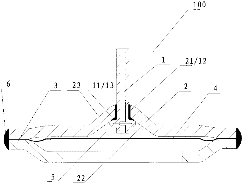
[0041] image 3 A structural schematic diagram of one of the specific embodiments of the thermal expansion valve gas box head part provided for the invention, Figure 8 It is a schematic diagram of the capillary structure in the above embodiment.

[0042] like image 3 and Figure 8 shown and see figure 1 . The thermal expansion valve includes a valve body 102 with an inner cavity 101, a flow channel inlet 103 and a flow channel outlet 104 communicated with the inner cavity 101 of the valve body 102, and an air box head arranged at one end of the valve body 102 A piece 100 and a valve part 104 disposed in the inner chamber 101.

[0043] Air box head part 100 comprises the air box seat body 3 and the air box cover body 2 that are welded into one, diaphragm 4 is arranged between the air box seat body 3 and the air box cover body 2, like this between the air box cover body 2 and the diaphragm An airtight temperature-sensing chamber 5 is formed between the sheets 4 . The ai...


PUM


Abstract

The invention relates to a gas tank header part of a thermal expansion valve and a machining method thereof, belonging to the technical field of refrigeration control. The gas tank header part comprises a gas tank cover body with an introduction hole, a gas tank seat body and a diaphragm sheet, wherein the gas tank cover body is welded with the gas tank seat body and the diaphragm sheet to form a temperature sensing chamber, and a capillary tube is welded on the introduction hole of the gas tank cove body. The gas tank head part is characterized in that the capillary tube is provided with a protrusion part connected with the gas tank cover body through welding. A combination method of the gas tank header part comprises the steps of: machining the protrusion part on an abutment or a curled edge of the capillary tube; penetrating the capillary tube through the introduction hole of the gas tank cover body; adding a high-temperature fusion material onto an outer edge surface and a protrusion end, corresponding to the gas tank cover, of the capillary tube to carry out welding; and welding the gas tank cover body, the gas tank seat body and the diaphragm to form the gas tank header part. By means of the structural improvement in the invention, the area of a welding contact region between the capillary tube and the gas tank cover is increased, and the welding reliability of the capillary tube is enhanced.

Description

technical field [0001] The invention belongs to the technical field of refrigeration control, is suitable for vapor compression heat pump systems, such as air-conditioning systems, etc., and specifically relates to an air box head part of a thermal expansion valve and a processing method thereof, and a thermal expansion valve using the part Background technique [0002] The thermal expansion valve as a throttling device is widely used in the circuits of refrigeration systems such as air conditioners, refrigerators, and heat pumps. It controls the flow of refrigerant in the refrigeration system by sensing the temperature change of the refrigerant at the end of the evaporator. It plays the role of throttling and reducing pressure and regulating the flow of refrigerant. The thermal expansion valve in the prior art has the structure disclosed in Chinese patent CN200520100993, that is, as figure 1 and figure 2 shown. [0003] Its thermal expansion valve includes a valve body 1...

Claims


Application Information

Patent Timeline
Patent Type & Authority Applications(China)
IPC IPC(8): F16K31/68F16K31/126F25B41/06
Inventor 陈伯汀宋红敏
Owner ZHEJIANG SANHUA INTELLIGENT CONTROLS CO LTD
Learn More