Hydraulic manipulator

A manipulator and hydraulic technology, applied in the direction of manipulators, program-controlled manipulators, manufacturing tools, etc., can solve the problems of complex manipulator structure, low action precision, unstable work performance, etc., and achieve simple structure, high position accuracy and broad market prospects Effect

Inactive Publication Date: 2012-05-16
徐亚超
View PDF0 Cites 3 Cited by
  • Summary
  • Abstract
  • Description
  • Claims
  • Application Information

AI Technical Summary

Problems solved by technology

[0002] At present, the structure of the manipulator for grabbing cylindrical objects is complicated, the working performance is unstable, and th

Method used


Image

  • Hydraulic manipulator
  • Hydraulic manipulator

Examples


Embodiment

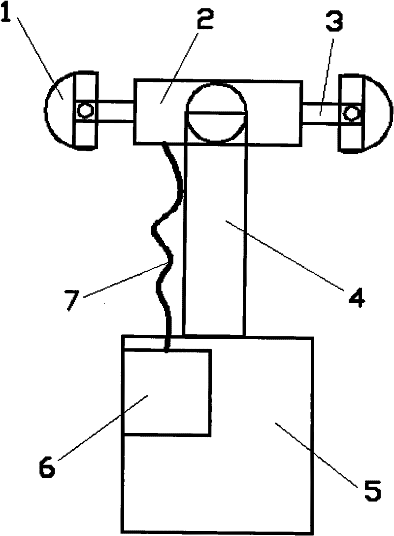
[0013] This embodiment provides that the present invention provides a hydraulic manipulator, which is characterized in that: the hydraulic manipulator includes a working part 1, a hydraulic cylinder 2, a piston rod 3, an arm 4, a base 5, a hydraulic pump 6, and a pipeline 7;

[0014] Wherein: the working part 1 is hinged with the piston rod 3, the piston rod 3 is installed inside the hydraulic cylinder 2, the arm 4 is hinged with the hydraulic cylinder 2, and the hydraulic cylinder 2 is connected with the hydraulic pump 6 installed in the base 5 through the pipeline 7.

[0015] There are two working parts 1 .

[0016] Said working part 1 is arranged symmetrically with respect to the hydraulic cylinder 2 .


PUM


Abstract

The invention relates to a hydraulic manipulator. The invention is characterized in that the hydraulic manipulator comprises a working portion, a hydraulic cylinder, a piston rod, an arm, a base, a hydraulic pump and a pipeline, wherein the working portion is hinged with the piston rod, the piston rod is arranged inside the hydraulic cylinder, the arm is hinged with the hydraulic cylinder, and the hydraulic cylinder is connected with the hydraulic pump arranged in the base by virtue of the pipeline. The hydraulic manipulator provided by the invention has the advantages of simple structure, high action positional precision and wide market prospect.

Description

technical field [0001] The invention relates to the field of mechanical structures, and in particular provides a hydraulic manipulator. Background technique [0002] At present, the structure of the manipulator for grabbing cylindrical objects is complex, the working performance is unstable, and the action accuracy is not high. In order to simplify the structure and improve the grasping accuracy, a suitable manipulator is urgently needed. Contents of the invention [0003] The purpose of the present invention is to provide a hydraulic manipulator in order to achieve simplicity and stable performance. [0004] The invention provides a hydraulic manipulator, which is characterized in that: the hydraulic manipulator includes a working part 1, a hydraulic cylinder 2, a piston rod 3, an arm 4, a base 5, a hydraulic pump 6, and a pipeline 7; [0005] Wherein: the working part 1 is hinged with the piston rod 3, the piston rod 3 is installed inside the hydraulic cylinder 2, the a...

Claims


Application Information

Patent Timeline
IPC IPC(8): B25J9/08B25J13/00
Inventor 徐亚超
Owner 徐亚超
Why Eureka
Try Eureka