Image display apparatus
An image display device, image technology, used in image communication, optics, instruments, etc.
- Summary
- Abstract
- Description
- Claims
- Application Information
AI Technical Summary
Problems solved by technology
Method used
Image
Examples
Embodiment 1
[0136] An image display device and a display panel according to this embodiment will be described with reference to the drawings.
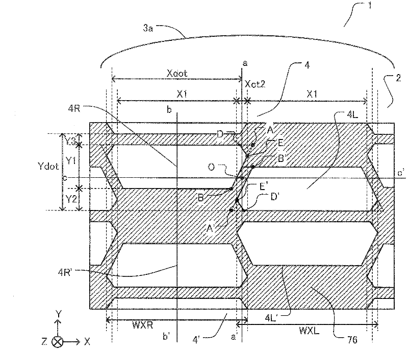
[0137] figure 1 is a plan view showing pixels of the display panel according to this embodiment.
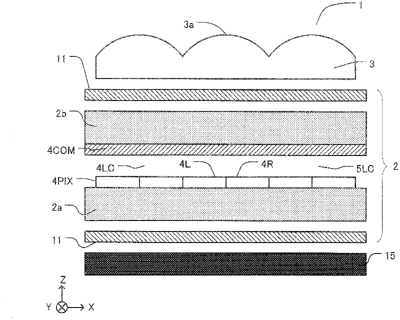
[0138] The display panel 2 is a three-dimensional display panel with two viewpoints, including pixels displaying an image of a first viewpoint and pixels displaying an image of a second viewpoint. In this embodiment, the first viewpoint pixel is the left-eye pixel 4L, and the second viewpoint pixel is the right-eye pixel 4R.
[0139] A pair of left-eye pixels 4L and right-eye pixels 4R constitutes the display unit 4 . When the focus is on one of the smallest unit pixels constituting the display unit 4 (the left-eye pixel 4L or the right-eye pixel 4R), it is called a “sub-pixel”. The sub-pixels are arranged in a matrix.
[0140] The cylindrical lens 3a is a one-dimensional lens having a circular convex portion. The cylindrical lenses 3a extend or ...
Embodiment 2
[0335] A pixel of a display panel according to a modified example of Embodiment 1 will be described with reference to the drawings.
[0336] Figure 20 is a plan view showing a pixel according to this embodiment.
[0337] The display panel 4 according to this embodiment includes sub-pixels for a plurality of viewpoints. The display panel 4 includes four sub-pixels 4S arranged along the X-axis direction. Each of the display panels 4' and 4" also includes four pixels 4S arranged in the X-axis direction.
[0338] The pixel 40 includes three display units 4, 4' and 4" arranged in the Y-axis direction and arranged in a matrix in the display area. The display units 4 in a single pixel are arranged in such a way that red R, green G and The blue B color filter extends along the X-axis direction. Four columns of sub-pixels VX1, VX2, VX3, and VX4 can classify image observations for four observation points and output images to the XZ plane as a display unit. Here, the order of colors ...
Embodiment 3
[0361] A pixel of a display panel according to Embodiment 3 of the present invention will be described with reference to the drawings.
[0362] Figure 22 is a plan view showing pixels of the display panel according to this embodiment.
[0363] The pixels of the display panel according to this embodiment are approximately trapezoidal, and are shaded by the outwardly curved upper and lower bases of approximately trapezoidal apertures.
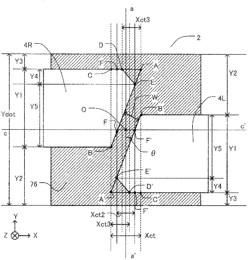
[0364] A subpixel has an aperture consisting of three ellipses and four tangents to which it is tangent. The ellipses are ellipses E5 and E5' having a center in the central part of the aperture, and two ellipses E3 or E3' and E4 or E4' at the lower base of the approximate trapezoidal shape. Ellipses E5 and E5' are identical. The ellipses E3 and E3' and E4 and E4' are respectively the same.
[0365] Points D, E and F are the tangent points between the line and the ellipse. At each point, the derivative of the vertical aperture width with res...
PUM
 Abstract
Description
Claims
Application Information
 - Generate Ideas
- Intellectual Property
- Life Sciences
- Materials
- Tech Scout
- Unparalleled Data Quality
- Higher Quality Content
- 60% Fewer Hallucinations
Browse by: Latest US Patents, China's latest patents, Technical Efficacy Thesaurus, Application Domain, Technology Topic, Popular Technical Reports.
© 2025 PatSnap. All rights reserved.Legal|Privacy policy|Modern Slavery Act Transparency Statement|Sitemap|About US| Contact US: help@patsnap.com


