
Navigation robot obstacle detection method and system

An obstacle detection and robot technology, applied in the field of robot navigation, can solve the problems that the speed of imaging cannot meet the application needs of autonomous mobile robots, the system has poor real-time performance, and the amount of image calculation is large, so as to reduce interference, improve accuracy, and improve detection range. Effect

Inactive Publication Date: 2012-05-09
CENT SOUTH UNIV
View PDF2 Cites 29 Cited by
  • Summary
  • Abstract
  • Description
  • Claims
  • Application Information

AI Technical Summary

Problems solved by technology

The image calculation required by machine vision technology is very large, the real-time performance of the system is poor, and the imaging speed cannot meet the application needs of autonomous mobile robots

Method used


Image

  • Navigation robot obstacle detection method and system
  • Navigation robot obstacle detection method and system
  • Navigation robot obstacle detection method and system

Examples


Embodiment Construction

[0038] The present invention will be described in further detail below in conjunction with accompanying drawing and specific embodiment:

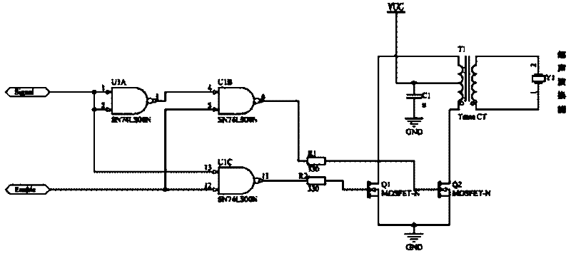
[0039] like figure 1 As shown, the core part of the detection system is the design of the 40kHz high-voltage drive signal generation module and the ultrasonic signal receiving adjustment module: the 40kHz square wave signal through the primary winding is boosted by the transformer, and the peak-to-peak output of the secondary winding is about 100V. Drive signal, using this signal to drive the ultrasonic transmitter, can increase the peak-to-peak signal of 12V to the peak-to-peak signal of 108V, to ensure the output power to drive the ultrasonic transmitter; the signal is relatively weak during the ultrasonic receiving adjustment process and needs to be amplified. AD sampling, the amplification circuit uses the instrumentation amplifier INA129P for the first stage amplification, the amplification factor is 100 times, and then the second sta...


PUM


Abstract

The invention discloses a navigation robot obstacle detection method and system. The system mainly comprises an ultrasonic detection module, an ultrasonic scanning module, an infrared detection compensation module and a robot core control module, wherein the ultrasonic detection module is mainly realized by amplifying a 40 kHz high-voltage driving signal and an ultrasonic receiving signal. The module is erected on a scanning steering engine to realize front non-dead-angle 180-degree scanning detection. By combining infrared range finding, the compensation of a navigation robot ultrasonic blind region is realized. A driving circuit is realized by establishing an H bridge with a field effect transistor. In a navigation robot, planar multi-point sensing is realized by using a pair of ultrasonic probes; the range finding range can reach 5.9 m at farthest; and a detection blind region is reduced to 2 cm. The system has the characteristics of low cost, small detection blind region, high anti-diffraction capacity, high real-time property and the like and has broad industrialization prospect. The method and the system can be used for the fields of micro robot navigation, environmental detection, intelligent vehicle active safety and the like.

Description

technical field [0001] The invention belongs to the technical field of robot navigation, and relates to a navigation robot obstacle detection method and system. Background technique [0002] Active safety and obstacle avoidance is one of the basic functions of navigation robots. There are a variety of implementation technologies: infrared technology, machine vision technology, laser technology, microwave radar technology and ultrasonic technology. However, these technologies have their own characteristics. The infrared resolution is up to 1um, and the measurement range is from tens of centimeters to 1 meter. It is mainly used for the detection of short-range obstacles. Machine vision technology has a wide detection range and the largest information, and it is difficult to distinguish the detection target from the background. The image calculation required is very large, and the real-time performance of the system is poor. The laser has good directionality, high precision a...

Claims


Application Information

Patent Timeline
Patent Type & Authority Applications(China)
IPC IPC(8): G01S15/93
Inventor 蔡自兴唐琎余伶俐尤作潘一啸
Owner CENT SOUTH UNIV
Learn More