
Gas-stove and ejecting system thereof

A technology of gas stoves and ejector tubes, applied in the field of gas stoves, can solve the problems of jacking up the handle, readjusting the damper, changing the opening of the damper, etc., and achieve the effect of reducing the possibility of misoperation

Inactive Publication Date: 2012-05-09
BSH ELECTRICAL APPLIANCES JIANGSU
View PDF7 Cites 2 Cited by
  • Summary
  • Abstract
  • Description
  • Claims
  • Application Information

AI Technical Summary

Problems solved by technology

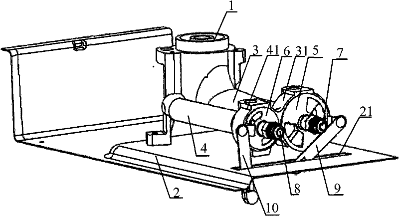
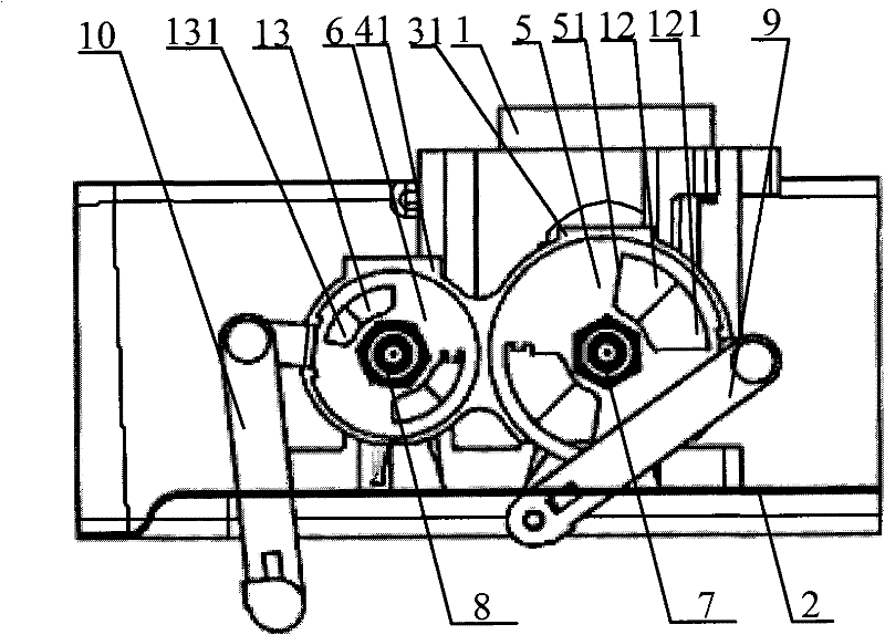
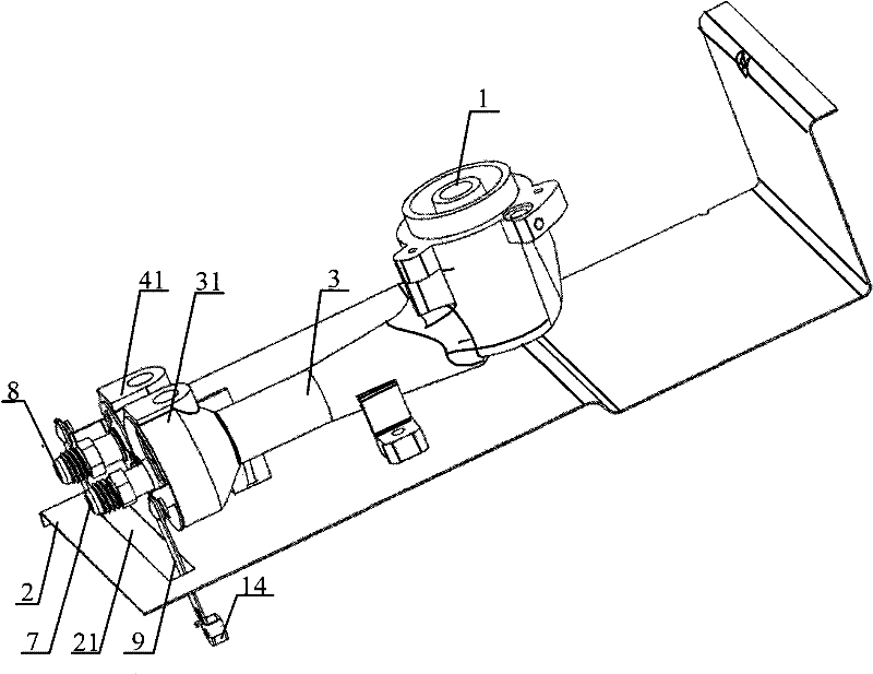
[0005] In an existing gas cooker, one end of the handle for adjusting the air door is fixed on the air door, and the other end directly extends out of the bottom surface of the bottom plate of the gas cooker. During the process, users often misoperate the handle. For example, when the gas stove is placed on the table, because the handle of the damper protrudes out of the bottom plate of the gas stove and the handle is directly fixed on the damper, when the bottom plate of the gas stove touches the table, The handle will touch the table, and the table will push the handle up to change the opening of the damper
In addition, such as embedded stoves, the countertop of the cabinet is made into a concave shape, and the gas stove can just be embedded in it. The gas stove and the countertop of the cabinet form a plane, but the handle of the damper protrudes beyond the bottom plate of the gas stove. Embedded in the cabinet, so the cabinet is located under the gas stove. When the user puts something in the cabinet, it is easy to misoperate the handle and the handle will be lifted up, thus changing the opening of the damper and changing the air flow in the mixing tube. Therefore, the above-mentioned handle fixed on the damper is easy to be lifted up directly during the use of the gas stove, thereby changing the opening of the damper, resulting in a change in the mixing ratio of liquefied combustible gas and air, causing the user to readjust the damper

Method used


Image

  • Gas-stove and ejecting system thereof
  • Gas-stove and ejecting system thereof
  • Gas-stove and ejecting system thereof

Examples


Embodiment Construction

[0037] In order to understand the technical solutions in the embodiments of the present invention more clearly, the technical terms appearing in the embodiments are now explained:

[0038] The radial side of the air inlet hole: the part of the side along the radial direction of the ejector pipe on the air inlet hole on the damper.

[0039] The following will clearly and completely describe the technical solutions in the embodiments of the present invention in conjunction with the accompanying drawings in the embodiments of the present invention. Obviously, the described embodiments are only some of the embodiments of the present invention, not all of them. Based on the embodiments of the present invention, all other embodiments obtained by persons of ordinary skill in the art without making creative efforts belong to the protection scope of the present invention.

[0040] The invention provides a gas cooker. By improving the damper on the mixing pipe in the injection system of...


PUM


Abstract

The embodiment of the invention discloses a gas-stove ejecting system comprising ejecting pipes, mixing pipes communicating with the ejecting pipes, nozzles arranged on air-inlet ends of the mixing pipes, air valves penetrating the nozzles and arranged on the mixing pipes, wherein the air valves can rotate around the nozzles, and handles with first ends hinged to the air valves. In the ejecting system provided by the embodiment of the invention, because the first ends of the handles are hinged to the air regulating valves, the handles are hinged to the air valves; because the handles are hinged to the air valves, when an external object contacts the handles, the handles can rotate with a certain extent, such that buffering is provided between the handles and the air valves, and the air valves are prevented from being directly jacked by the handles. Therefore, misoperation of users on the air valves can be avoided. The invention also provides a gas-stove with the ejecting system.

Description

technical field [0001] The present invention relates to the technical field of cooker manufacturing, and more specifically, relates to an injection system of a gas cooker, and also relates to a gas cooker with the above-mentioned injection system. Background technique [0002] Gas stoves are household stoves commonly used in people's daily life, and gas stoves are mainly stoves that burn with liquefied combustible gas as fuel. The liquefied combustible gas can be natural gas, liquefied petroleum gas, biogas, etc. According to the different types of liquefied combustible gas, gas stoves can be divided into various types, such as liquefied gas stoves, coal gas stoves, natural gas stoves, etc. Of course, gas stoves can also be divided into single stoves, double stoves, single-eye stoves, multi-eye stoves, desktop stoves, embedded stoves, etc. according to their different structures. [0003] The mixing tube arranged on the gas stove intake side is an important part of the gas ...

Claims


Application Information

Patent Timeline
IPC IPC(8): F24C3/08
Inventor 顾学彬博建安・克里斯丁朱卫宏
Owner BSH ELECTRICAL APPLIANCES JIANGSU
Learn More