
Method for positioning and forming hidden and buried grotto in geomechanical model test

A model test and geomechanics technology, applied in underground chambers, earthwork drilling, mining equipment, etc., can solve problems such as easy formation of joints, great influence on test results, discontinuous physical and mechanical parameters, etc., to improve accuracy and Accuracy, even and dense material around the hole, and smooth inner wall

Inactive Publication Date: 2013-10-30
SHANDONG UNIV
View PDF2 Cites 0 Cited by
  • Summary
  • Abstract
  • Description
  • Claims
  • Application Information

AI Technical Summary

Problems solved by technology

The disadvantage of this method is that the inner wall of the cavity is easy to form joints, and the physical and mechanical parameters between the prefabricated blocks are discontinuous, which greatly affects the test results.
With this method, the excavation of concealed caverns needs to be positioned on the basis of the excavated caverns of the previous level, and the excavation of caverns with variable cross-sections cannot be carried out.
[0007] (4) The invention patent with application number 201110067678.8 proposes a cavity-forming device for buried caverns in underground engineering test models, but the patent does not introduce the positioning and forming methods of buried caverns in models

Method used


Image

  • Method for positioning and forming hidden and buried grotto in geomechanical model test
  • Method for positioning and forming hidden and buried grotto in geomechanical model test
  • Method for positioning and forming hidden and buried grotto in geomechanical model test

Examples


Embodiment Construction

[0027] The present invention will be further described below in conjunction with the accompanying drawings and embodiments.

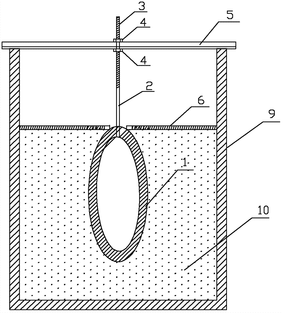
[0028] figure 1 Among them, a positioning steel rod 2 is fixed in the middle of the top of the cavity wooden formwork 1, and a precision thread 3 is tapped on the positioning steel rod 2, and the positioning steel rod 2 is connected with the steel frame set on the model frame 9 through the positioning bolt 4. Beam 5 is connected. Translating the steel beam 5 and rotating the positioning bolt 4 to move the positioning steel rod 2 up and down can realize the precise positioning of the buried cavity.

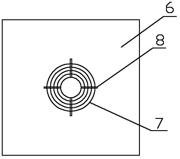
[0029] figure 2 , 3 There is a circular hole in the middle of the high-strength pressure plate 6, and a plurality of concentric and detachable steel collars 7 with different diameters are arranged on the outside of the hole. The steel collars 7 are connected together by inner hole pins 8, and the steel collars 7 is composed of several concentric rings c...


PUM


Abstract

The invention relates to a method for positioning and forming a hidden and buried grotto in a geomechanical model test. The method comprises the following steps of: 1) manufacturing a wooden mould which has the same shape as the grotto, fixing a positioning steel rod in the middle at the top of the wooden mould of the grotto, connecting the positioning steel rod with a steel cross beam on a model frame through a positioning bolt, and moving the positioning steel rod up and down by translating the steel cross beam and rotating the positioning bolt to position the hidden and buried grotto precisely; 2) according to the spatial shape of the wooden mould of the grotto, manufacturing a high-strength pressing plate with steel lantern rings which are concentric and have different diameters, and compacting a model material layer by layer by using the high-strength pressing plate; and 3) moving the positioning steel rod up by rotating the positioning bolt, and pulling out the wooden mould to form a modeled hidden and buried grotto. By adopting the method, the modeled hidden and buried grottoes with different shapes and different diameters can be manufactured; the spatial precise positioning of the hidden and buried grotto can be realized; the interference of the model material on the periphery of the grotto in the grotto forming process is reduced; and standard shape, smooth inner wall and uniform and compact peripheral material of the grotto are effectively ensured.

Description

technical field [0001] The invention relates to a method for positioning and forming a buried cavern in a geomechanical model test, and mainly relates to a method for positioning and forming a buried cavern in deep underground engineering geomechanical model tests in the fields of energy, resources and national defense engineering. Background technique [0002] In recent years, my country's economic development has become more and more rapid, and the requirements for infrastructure construction have continued to increase. With the continuous development of the national economy, a large number of large-scale underground projects in the fields of hydropower, transportation, energy, and national defense have started construction one after another. Due to its concealment and complexity, underground engineering requires theoretical research on the one hand and model tests on the other. Under the condition of basically satisfying the principle of similarity, the geomechanical mod...

Claims


Application Information

Patent Timeline
Patent Type & Authority Patents(China)
IPC IPC(8): E21D13/02
Inventor 张强勇李术才向文段抗刘健贾超蔡兵曹冠华许孝滨
Owner SHANDONG UNIV
Learn More