
Compensation calculation method of heavy load phase of brushless direct current (DC) motor without position sensor

A technology of brush DC motor and phase compensation, applied in the direction of electronically commutated motor control, electrical components, electronic commutator, etc., can solve waveform distortion, which is not conducive to reducing torque ripple of brushless DC motor, and cannot ensure commutation Properly proceeding etc.

Inactive Publication Date: 2012-05-02
WEIHAI CREDITFAN VENTILATOR
View PDF2 Cites 49 Cited by
  • Summary
  • Abstract
  • Description
  • Claims
  • Application Information

AI Technical Summary

Problems solved by technology

Its shortcoming is: by detecting the three-phase terminal voltage, performing deep filtering and then comparing with the analog neutral point, the rotor position signal is generated, but due to the large current and long freewheeling time under heavy load, it will affect the "ideal" The voltage waveform of the three-phase terminal causes waveform distortion, which affects the accuracy of the detected position signal, cannot ensure the correct commutation, and the phase angle delay commutation is not conducive to reducing the torque ripple of the brushless DC motor
[0007] Therefore, this is also the main technical difficulty in the application of the position sensorless control method in the high-power field

Method used

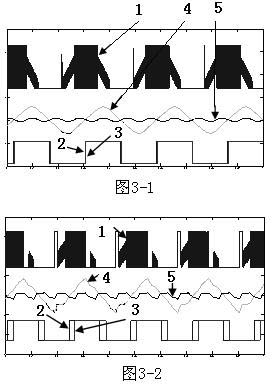

Image

  • Compensation calculation method of heavy load phase of brushless direct current (DC) motor without position sensor
  • Compensation calculation method of heavy load phase of brushless direct current (DC) motor without position sensor
  • Compensation calculation method of heavy load phase of brushless direct current (DC) motor without position sensor

Examples


Embodiment Construction

[0058] Below in conjunction with accompanying drawing, the present invention is further described:

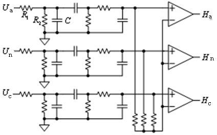
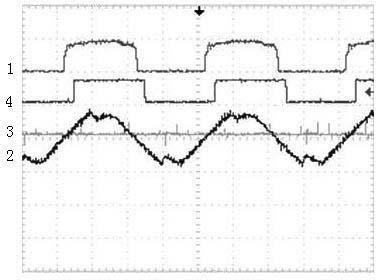
[0059] As shown in the accompanying drawing, a position sensorless brushless DC motor heavy-duty phase compensation calculation method is characterized in that it adopts a rice electromotive force detection method, through a counter electromotive force detection circuit (such as figure 1 ) to detect the three-phase terminal voltage, and then compare it with the analog neutral point after deep filtering by the filter circuit, and generate the rotor position signal through the DSP processor. This method will affect the The "ideal" three-phase terminal voltage waveform causes waveform distortion and affects the accuracy of the detected position signal, as shown in the attached figure 2 Shown is the experimental waveform of the position detection signal under heavy load, in which signal 1 is the back EMF detection signal, and signal 4 is the Hall position detection signal. Obvious...


PUM


Abstract

The invention relates to the technical field of brushless direct current (DC) motors, and in particular relates to a compensation calculation method of the heavy load phase of a brushless DC motor without a position sensor. The method is characterized by adopting a back electromotive force detection method to detect the three-phase terminal voltage with a back electromotive force detection circuit, carrying out depth filtering with a filter circuit, comparing the voltage with an analog neutral point, generating a rotor position signal with a digital signal processor (DSP), dividing the terminal voltage into a back electromotive force signal and a follow current interference signal, calculating the phases and amplitudes of the two signals to obtain a phase advance angle, caused by the follow current, of the rotor position signal and compensating the phase advance angle. The method has the following beneficial effects that: the controller can determine the phase advance angle in real time by only detecting the phase current of the motor; and phase angle compensation can be appropriately carried out according to the current and the rotating speed as the advance phase change of the phase angle is beneficial to the reduction of the torque ripple of the brushless DC motor, thus ensuring the motor to reach the best operation state.

Description

technical field [0001] The invention relates to the technical field of brushless direct current motors, in particular to a calculation method for heavy-load phase compensation of a position sensorless brushless direct current motor. Background technique [0002] Brushless DC Motor (Brushless DC Motor, hereinafter referred to as BLDC) has been fully developed in the world due to its high reliability, high efficiency, convenient speed regulation, and long life. In some more developed countries, brushless DC Electric motors will become the dominant motor in the next few years and gradually replace other types of motors. [0003] BLDC drive control methods are divided into two types: position sensor type and position sensorless type. The existence of the position sensor will bring a lot of defects and inconvenience to the application of the brushless motor. First, the position sensor will increase the volume and cost of the motor; secondly, connecting many position sensors will...

Claims


Application Information

Patent Timeline
Patent Type & Authority Applications(China)
IPC IPC(8): H02P6/18H02P6/10H02P6/182
Inventor 孟凡民徐殿国杨明曹何金生王公旺
Owner WEIHAI CREDITFAN VENTILATOR
Learn More