
Marsh gas collection and storage floater and marsh gas compression conveyor using same

A biogas collection and biogas technology, applied in the field of biogas, can solve the problems of scooping biogas liquid, inconvenient feeding, complicated manufacturing process, long working hours, etc., and achieve the effect of convenient and economical transportation

Inactive Publication Date: 2013-07-24
徐文辉
View PDF2 Cites 0 Cited by
  • Summary
  • Abstract
  • Description
  • Claims
  • Application Information

AI Technical Summary

Problems solved by technology

[0002] The existing floating cover type biogas collection conveyor has a structure including a floating cover, a main tank body, a sealed water tank, a feed pipe and a discharge pipe, etc. The manufacturing process is complex, requiring many materials, long working hours, and high manufacturing costs , and when discharging, it is necessary to remove the floating cover first to expose the pit pond, and it is not convenient to scoop biogas slurry and feed materials at ordinary times

Method used


Image

  • Marsh gas collection and storage floater and marsh gas compression conveyor using same
  • Marsh gas collection and storage floater and marsh gas compression conveyor using same
  • Marsh gas collection and storage floater and marsh gas compression conveyor using same

Examples


Embodiment 1

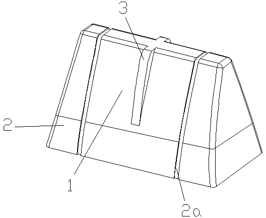
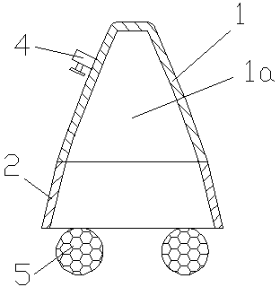
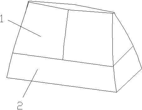
[0029] Embodiment 1: As shown in the figure, the biogas collection and storage buoyant device of this embodiment includes a cover body 1, which is provided with a biogas collection and storage chamber 1a that gradually shrinks from the mouth to the top, and the inner and outer walls of the cover body 1 The shapes are the same, the ratio of the length of the top of the cover to the length of the mouth of the cover is 0.997, and the ratio of the width of the top of the cover to the width of the mouth of the cover is 0.15. Of course, in specific implementation, the ratio of the length of the top of the lid to the length of the mouth of the lid can be other values ​​in the range of 0.65-0.997, and the ratio of the width of the top of the lid to the width of the mouth of the lid can be other values ​​in the range of 0.15-0.4. The shape of the cover body 1 with values ​​within this range presents an obvious upper-smaller-lower-large shape, which is conducive to making the biogas in t...

Embodiment 2

[0037] Embodiment 2. The difference between the methane storage buoyant device of this embodiment and Embodiment 1 is that the ratio of the length of the top of the cover to the length of the mouth of the cover is 0.65, and the ratio of the width of the top of the cover to the width of the mouth of the cover is 0.4; Other structures of the methane storage buoyant are the same as those in Embodiment 1.

Embodiment 3

[0038] Embodiment 3, the difference between the biogas storage and storage lifter of this embodiment and Embodiment 1 is that the ratio of the length of the top of the cover to the length of the mouth of the cover is 0.75, and the ratio of the width of the top of the cover to the width of the mouth of the cover is 0.25; Other structures of the methane storage buoyant are the same as those in Embodiment 1.


PUM


Abstract

The invention discloses a marsh gas collection and storage floater, which comprises a cover body, wherein the cover body is provided with a marsh gas collection and storage cavity gradually reduced from the mouth to the top; the inner wall and the outer wall of the cover body are in the same shape; the length ratio of the top to the mouth of the cover body is 0.65 to 0.997, and the width ratio ofthe top to the mouth of the cover body is 0.15 to 0.4; and the floater is positioned and stabilized through coordination of the plane shape and the size of the top of the cover body and a pressure plate or a pressure rod. The mouth of the marsh gas collection and storage cavity of the gradually reduced structure can cover the marsh gas liquid level of a large range, so the collection range of themarsh gas is wide; after the floater is put into the marsh gas liquid, the pressure of the marsh gas is quickly raised, so that the marsh gas is output more fully; and a plurality of marsh gas collection and storage floaters can be superposed together, so that transportation is facilitated. The invention also discloses a marsh gas compression conveyor, which has a few structural components and low construction cost; and when the marsh gas compression conveyor is constructed, only the pressure plate on the mouth of a pit is pressed on the top of the marsh gas collection and storage floater, sothe marsh gas compression conveyor is convenient and fast to install and can be directly used for a conventional manure pit under a corral.

Description

technical field [0001] The invention relates to the field of biogas, in particular to a biogas collection device and a biogas pit. Background technique [0002] The existing floating cover type biogas collection conveyor has a structure including a floating cover, a main tank body, a sealed water tank, a feed pipe and a discharge pipe, etc. The manufacturing process is complex, requiring many materials, long working hours, and high manufacturing costs , and when discharging, it is necessary to remove the floating cover first to expose the pit pond, and it is not convenient to scoop biogas slurry and feed materials at ordinary times. [0003] Therefore, it is necessary to improve the floating cover biogas collection conveyor in the prior art, so that it has the advantages of simple structure, convenient slag discharge, convenient overlapping transportation, convenient manufacturing and installation, low manufacturing cost, and high reliability. Contents of the invention ...

Claims


Application Information

Patent Timeline
Patent Type & Authority Patents(China)
IPC IPC(8): C12M1/107
CPCY02E50/343C12M21/04C12M41/40C12M23/38Y02E50/30
Inventor 徐文辉
Owner 徐文辉
Learn More