
Remote ammeter system

A technology of remote electric meters and electric meters, which is applied in the field of monitoring, can solve problems such as trends that cannot become mainstream development, reading pulse meter reading counting in and out, disputes between management departments and users, and achieve unlimited access locations, low setup costs, and maintenance low cost effect

Inactive Publication Date: 2016-04-27
镇江石鼓文智能化系统开发有限公司
View PDF5 Cites 2 Cited by
  • Summary
  • Abstract
  • Description
  • Claims
  • Application Information

AI Technical Summary

Problems solved by technology

Facts have proved that the reliability of these links cannot be guaranteed, and there are often disadvantages in use. Due to factors such as the jitter of the dial and electromagnetic interference in the transmission process, it is easy to cause pulse loss or over-counting pulses.
Therefore, after a period of use, the meter reading data of the pulse counting method is inconsistent with the on-site reading value of the meter, and the system needs to be continuously corrected, which may easily cause disputes between the management department and the user.
2) The installation of the meter sensor is also an important factor. At present, some water meter manufacturers purchase the sensor from the sensor manufacturer and install it by themselves. Because the pointer in the water meter is a metal pointer due to careless installation, the pointer will even appear to the magnet after the water meter is installed and running. The problem of attracting to the magnet caused a large discrepancy between the field reading and the count of the pulse meter
[0004] Based on the above reasons, it can be clearly seen that the current meter reading method using the cumulative pulse method for metering cannot become the mainstream development trend in the future.
The root cause is the technical problems in the early stage of the current meter reading system, which is due to the inherent deficiencies in its product design. Using it directly as the basis for metering and charging will inevitably lead to disputes

Method used


Image

  • Remote ammeter system
  • Remote ammeter system
  • Remote ammeter system

Examples


Embodiment Construction

[0039] In order to better understand the technical content of the present invention, the specific embodiments are specifically cited and described as follows in conjunction with the accompanying drawings:

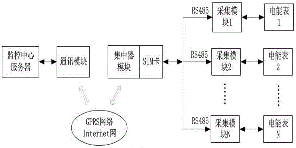
[0040] refer to figure 1 As shown, it includes monitoring center, concentrator, collector and user electric meter; its communication is divided into two layers, including the bottom layer communication between concentrator and collector and the upper layer communication between monitoring center and concentrator; the system constructed in this paper consists of four Partial composition: monitoring center, concentrator, collector and user meter; it is divided into two-layer structure, including the bottom layer communication between the concentrator and the collector and the upper layer communication between the monitoring center and the concentrator; the communication channel scheme of the system includes the concentrator and the concentrator. The underlying communication c...


PUM


Abstract

The invention provides a remote ammeter system. The remote ammeter system comprises a monitoring center, a concentrator, a collector and a user ammeter. According to the invention, communication is divided into a two-layer structure, the concentrator is communicated to a bottom layer of the collector, and the monitoring center is communicated to an upper layer of the concentrator. The system has the advantages that because a GPRS wireless public network platform is employed, the system can be used when the system is arranged, special wiring is not required for remote meter reading, and the remote ammeter system has the advantages of less investment at an early stage, fast effectiveness, and low upgrading and maintenance cost at anaphase.

Description

technical field [0001] The invention relates to the technical field of monitoring, in particular to a remote electric meter system. Background technique [0002] With the continuous improvement of living standards, smart communities and smart homes have gradually been recognized and accepted by people. Water, electricity, gas, and heating have become an indispensable part of it. The intelligent remote meter reading system is one of the subsystems of the integrated management system of the intelligent community. It has automatic remote meter reading and billing management for water, electricity, gas, and heating meters. It solves the problems of time-consuming, labor-intensive, large data errors and disturbing the people in the traditional manual meter reading method, which brings great convenience to people's social production and life. The design and realization of the intelligent remote meter reading system has certain theoretical value and high practicality. Automatic m...

Claims


Application Information

Patent Timeline
IPC IPC(8): G08C17/02
Inventor 杜峥
Owner 镇江石鼓文智能化系统开发有限公司
Learn More