Vibrating tray with adjustable feeding output

A vibrating plate and feeding technology, which is applied in the direction of vibrating conveyors, conveyors, conveyor objects, etc., can solve the problems of reducing production efficiency and increasing equipment costs, and achieve the effect of reducing supporting costs and improving quality

Inactive Publication Date: 2013-11-06
WENZHOU ZHONGKE AUTOMATION EQUIP
View PDF5 Cites 2 Cited by
  • Summary
  • Abstract
  • Description
  • Claims
  • Application Information

AI Technical Summary

Problems solved by technology

If you want to produce a new product, you need to bring samples to manufacture the vibration plate manufacturer to customize the top plate. This has caused great resistance to the rapid launch of new products on the market, seriously reduced production efficiency, and increased equipment costs a lot.

Method used


Image

  • Vibrating tray with adjustable feeding output
  • Vibrating tray with adjustable feeding output
  • Vibrating tray with adjustable feeding output

Examples


Embodiment 1

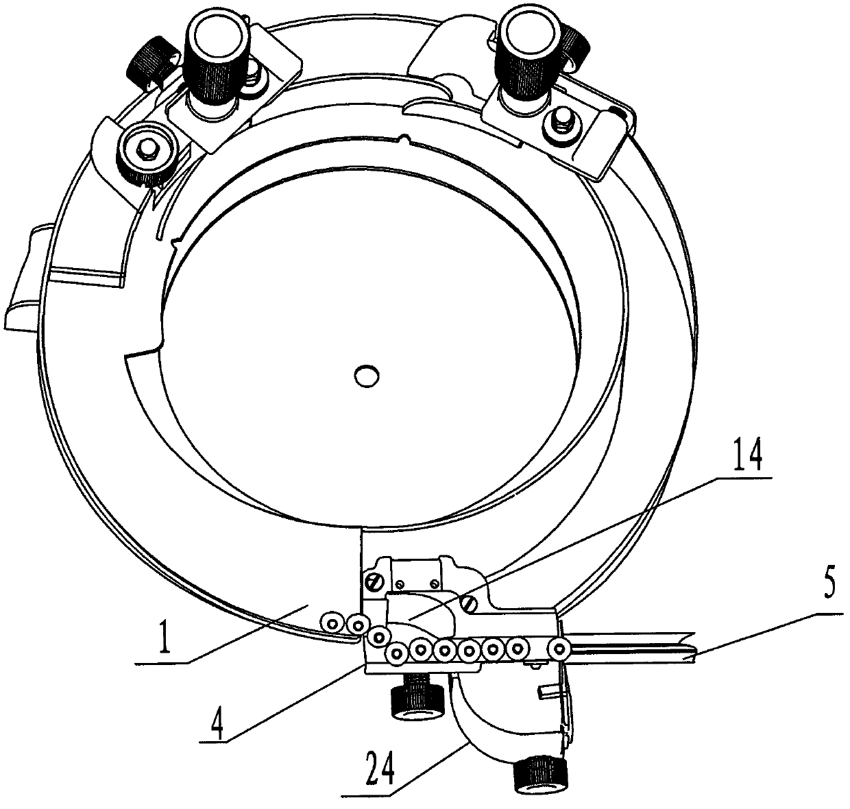
[0021] Such as Figure 1-Figure 3 As shown, this embodiment includes a top plate 3 , a top plate spiral slideway 1 , a feed output transition connection slideway 4 , a slideway support 2 and a return box 24 .

[0022] Such as figure 2 As shown, the slideway support 2 is fixed on the top plate 3, the feeding output transition connection slideway 4 is fixed on the slideway support 2, and the input end of the feeding output transition connection slideway 4 is connected to the The outlet of the top plate spiral slideway 1 is connected, and the output end of the transitional connection slideway 4 of the feeding output is connected with the entrance of the material receiving slideway 5 of the next machine.

[0023] The return box 24 is arranged below the feeding output transition connecting slideway 4 and is fixed on the slideway support 2, so that it can centrally recycle the workpieces accidentally dropped during the conveying process and reduce the recycling workload. .

[00...

Embodiment 2

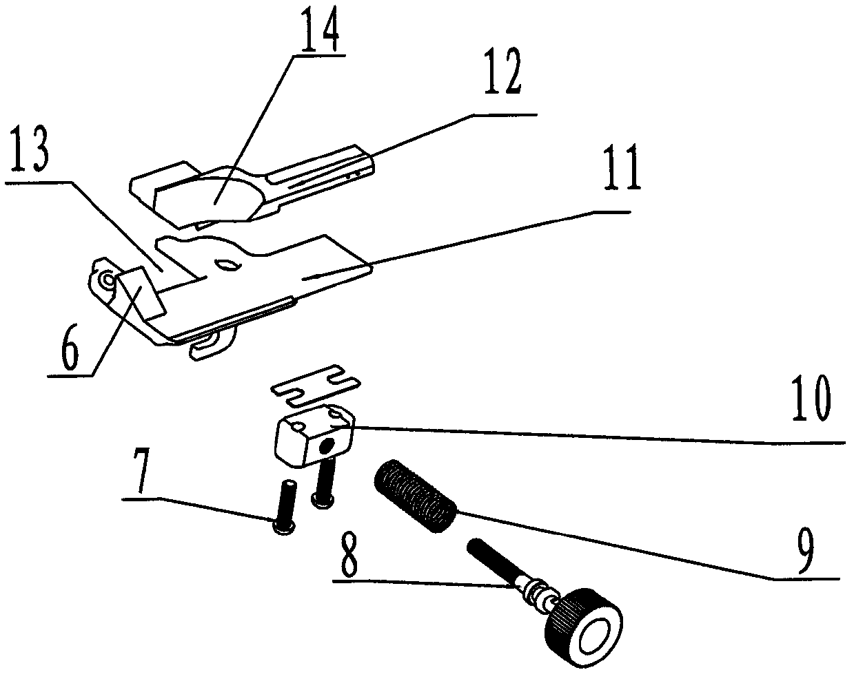
[0029] Such as figure 1 , Figure 4 , Figure 5 As shown, this embodiment includes a top plate 3 , a top plate spiral slideway 1 , a feeding output transition connection slideway 4 , a slideway support 2 , a workpiece turning and receiving device 16 and a return box 24 .

[0030] Such as figure 1 , Figure 4 As shown, the slideway support 2 is fixed on the top plate 3, the feeding output transition connection slideway 4 is fixed on the slideway support 2, and the input end of the feeding output transition connection slideway 4 is connected to the The outlet of the top plate spiral slideway 1 is connected, and the outlet of the feeding output transition connection slideway 4 is connected with the material inlet of the workpiece turning material receiving device 16, and the outlet of the workpiece turning material receiving device 16 is connected to the next machine. Material chute 5 entrances are connected.

[0031] The return box 24 is arranged below the feeding output tr...


PUM


Abstract

The invention relates to a vibrating tray for conveying and feeding workpieces to automatic mechanical equipment, in particular to a vibrating tray with adjustable feeding output. The vibrating tray comprises a top tray, a spiral slideway of the top tray, a feeding output transition connecting slideway and a slideway support and is characterized in that the feeding output transition connecting slideway comprises a slideway bottom plate fixed with an slideway outer side plate, an inner side moving plate of the slideway and an adjusting device of the inner side moving plate of the sideway; and the inner side moving plate of the slideway is connected with the adjusting device of the inner side moving plate of the slideway. The invention aims to design a vibrating tray with adjustable feeding output for adjusting the transition connecting slideway according the sizes and shapes of the workpieces and realizing conveying of different workpieces by a vibrating top tray. Compared with the prior art, the vibrating tray has the advantages that the manufacturing cost is lowered, the mass production is realized, the matching cost of the automatic mechanical equipment is reduced, the feeding output adjustment is convenient, and the working efficiency is high, etc.

Description

technical field [0001] The invention relates to a vibrating plate for conveying workpieces to automatic mechanical equipment, in particular to a vibrating plate with adjustable feeding and output. Background technique [0002] At present, the vibrating plate is the main device for the front end of the automatic mechanical equipment to arrange and transport the workpieces. Among them, there is a connecting slideway with fixed specifications and sizes between the top plate outlet of the vibrating plate and the input end of the automatic equipment slideway. Due to the variety of workpiece specifications and shapes, manufacturers often have to purchase corresponding vibrating top plates according to different types of workpieces. In particular, a specific treatment plan must be designed for a workpiece, so it is difficult to use molds to produce vibrating top plates during manufacturing. craft. The production of the vibrating top plate can only be completed by manual and mechan...

Claims


Application Information

Patent Timeline
Patent Type & Authority Patents(China)
IPC IPC(8): B65G27/10B65G47/24
Inventor 吴圣明庄瑞国
Owner WENZHOU ZHONGKE AUTOMATION EQUIP
Why Eureka
Try Eureka