
Method for preventing deformation of reinforcement steel plate welded on top flange of crane girder

A crane girder and flange technology, applied in the field of crane girder welding, can solve the problems of affecting the normal operation of the crane, the deformation of the reinforcing steel plate, and the unsatisfactory use, etc., and achieve the effect of simple structure, reducing deformation, and eliminating welding stress

Inactive Publication Date: 2012-05-02
GUIYANG AL-MG DESIGN & RES INST
View PDF4 Cites 12 Cited by
  • Summary
  • Abstract
  • Description
  • Claims
  • Application Information

AI Technical Summary

Problems solved by technology

[0002] At present, many existing crane girders cannot be installed on the track because the design is too narrow, and a wider reinforcing steel plate must be repaired and welded on it before they can be used, that is, the reinforcing steel plate is directly welded to the crane girder by ordinary welding. However, when the existing method is used for welding, the reinforcing steel plate will often be deformed due to welding, which will not only affect the installation of the track, but also affect the normal operation of the crane
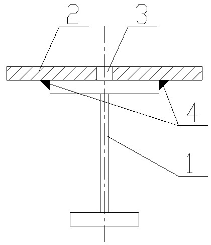
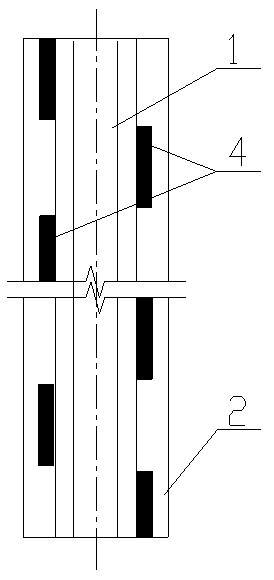
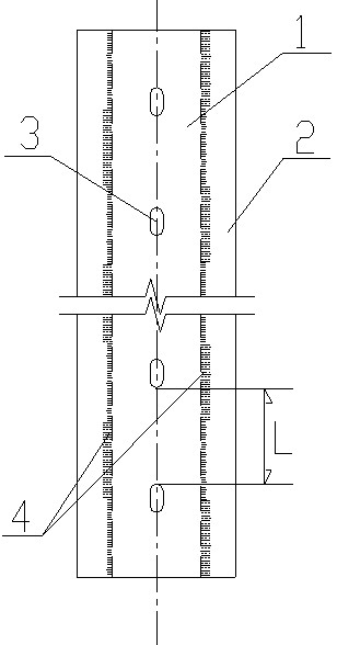
Therefore the existing method of welding reinforcing steel plates on the upper flange of the crane girder is still not ideal enough and cannot meet the needs of use.

Method used


Image

  • Method for preventing deformation of reinforcement steel plate welded on top flange of crane girder
  • Method for preventing deformation of reinforcement steel plate welded on top flange of crane girder
  • Method for preventing deformation of reinforcement steel plate welded on top flange of crane girder

Examples


Embodiment Construction

[0013] The present invention will be further described in detail below in conjunction with the accompanying drawings and embodiments.

[0014] Embodiment of the present invention: when welding the reinforced steel plate 2 to the upper flange of the existing crane girder 1, a method of preventing the deformation of the reinforced steel plate welded on the upper flange of the crane girder of the present invention is used for welding, that is, first At least 3 through holes 3 are made at the position of the center line along the length direction on the reinforced steel plate 2, the through holes 3 on the reinforced steel plate 2 are preferably made into oval holes, and can also be made into round holes, the elliptical holes The width or diameter of the round hole can be determined according to the needs. Generally, it can be selected within the range of 6-30 mm. The length of the elliptical hole can be selected within the range of 10-60 mm. The distance L is controlled at 200-500...


PUM


Abstract

The invention discloses a method for preventing the deformation of a reinforcement steel plate welded on a top flange of a crane girder. When the reinforcement steel plate is welded on the top flange of the crane girder, firstly, at least 3 through holes are made in the centerline position of the reinforcement steel plate along the length direction, the reinforcement steel plate is placed on the top flange of the crane girder, and the positions between edges at two sides of the top flange of the crane girder and the reinforcement steel plate are welded. The welding method comprises the following steps of: (1) intermittent welding; and (2) alternate repair welding on both sides. The method for performing intermittent welding and alternate repair welding on the edges at two sides of the top flange of the crane girder is adopted and the through holes are made on the reinforcement steel plate, not only the welding stress generated during welding can be effectively eliminated, but also the deformation of the reinforcement steel plate during welding can be effectively prevented. The method not only can effectively reduce and prevent the possibility of deformation when the reinforcement steel plate is welded on the top flange of the crane girder, but also has the advantages of simple structure and convenience for construction.

Description

technical field [0001] The invention relates to a method for preventing the deformation of a welding reinforcement steel plate on the upper flange of a crane girder, and belongs to the technical field of crane girder welding. Background technique [0002] At present, many existing crane girders cannot be installed on the track because the design is too narrow, and a wider reinforcing steel plate must be repaired and welded on it before they can be used, that is, the reinforcing steel plate is directly welded to the crane girder by ordinary welding. However, when using the existing method for welding, the reinforcement steel plate will often be deformed due to welding, which will not only affect the installation of the track, but also affect the normal operation of the crane. Therefore the existing method of welding reinforcing steel plates on the upper flange of the crane girder is still not ideal enough and cannot meet the needs of use. Contents of the invention [0003]...

Claims


Application Information

Patent Timeline
IPC IPC(8): B23K31/02
Inventor 吴在云王慧莹
Owner GUIYANG AL-MG DESIGN & RES INST
Learn More