
High rise building and fixed fire fighting system thereof

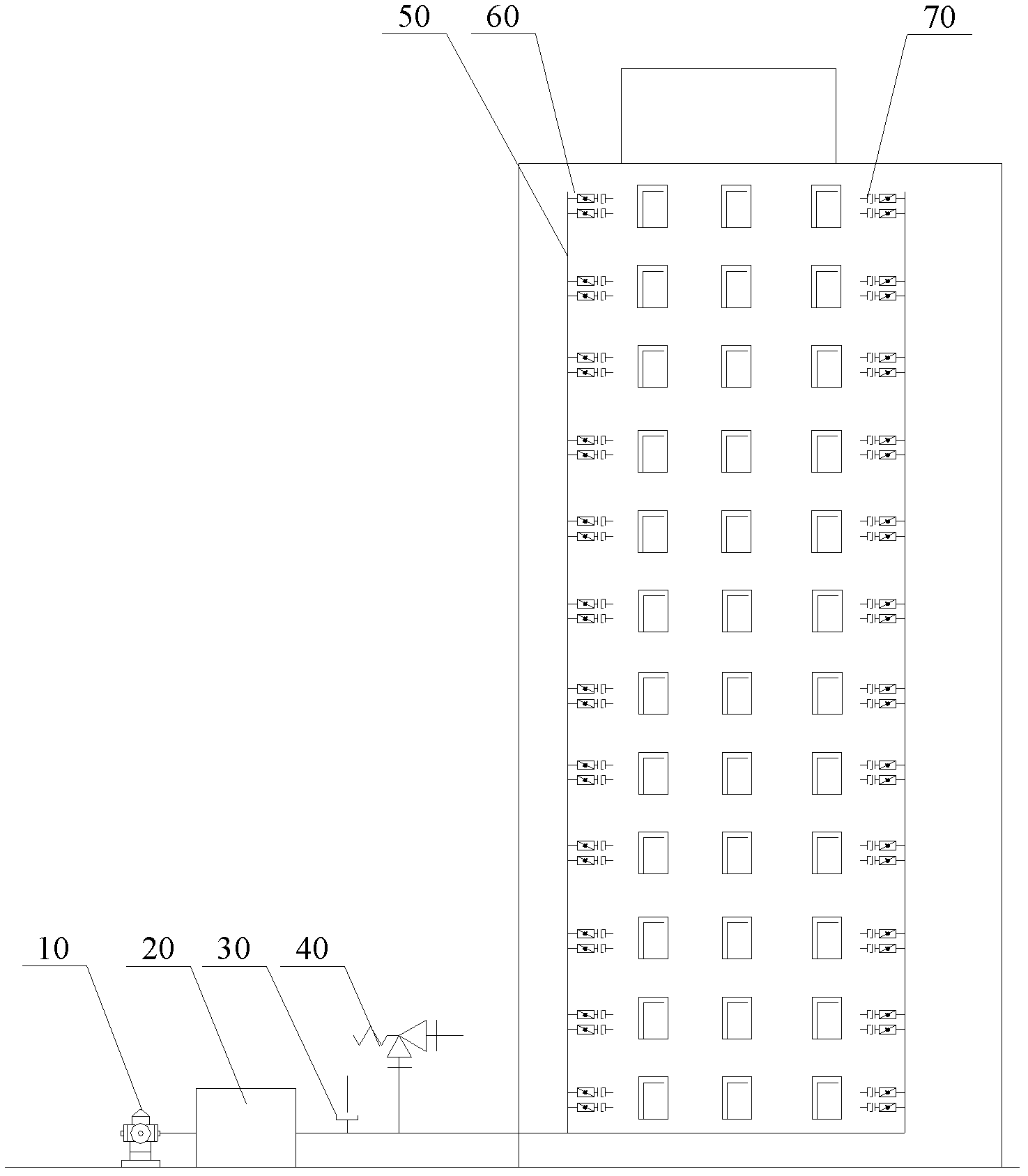
A technology for high-rise buildings and firefighting systems, applied in fire rescue and other directions, can solve problems such as insufficient water supply pressure, inability to effectively extinguish fires, and inability of fixed firefighting facilities to effectively meet the water consumption for firefighting, and achieve the effect of preventing internal leakage and optimizing design.

Active Publication Date: 2012-04-25
XCMG FIRE FIGHTING SAFETY EQUIP CO LTD
View PDF11 Cites 4 Cited by
  • Summary
  • Abstract
  • Description
  • Claims
  • Application Information

AI Technical Summary

Problems solved by technology

The disadvantage is that the indoor fire hydrant can only reach a maximum of 40L / s, and the pressure is only 2.5Mpa. Regardless of the pressure loss of the fire standpipe, it can only be effective for super high-rise buildings below 250 meters
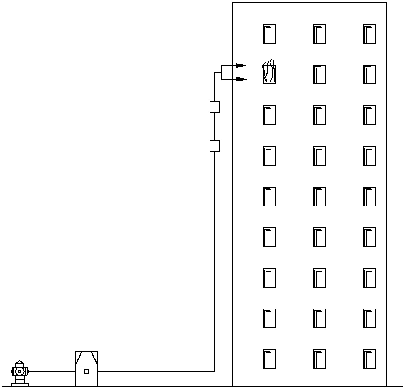
[0007] The above analysis shows that when a fire breaks out in an existing high-rise building, on the one hand, the outlet pressure of the existing fire truck is generally 2.0 MPa, and the pressure after entering the pipeline loss and reaching a height of more than 100 meters can only be below 0.4 MPa. Effectively extinguish super-high-rise fires; on the other hand, its fixed fire-fighting facilities cannot effectively meet the requirements of fire-fighting water consumption. At present, ordinary fire pumps can only send water to a height of about 100 meters, and fires occur on higher floors. Finally, the pressure of the water supply is not enough, and then the spread of the fire cannot be controlled, resulting in irreparable major losses

Method used


Image

  • High rise building and fixed fire fighting system thereof
  • High rise building and fixed fire fighting system thereof
  • High rise building and fixed fire fighting system thereof

Examples


Embodiment Construction

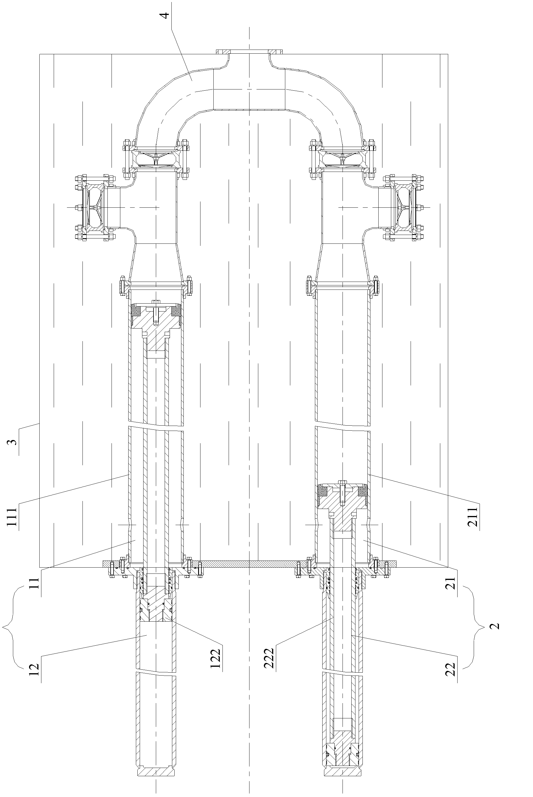
[0032] The core of the present invention is to provide a hydraulically controlled double plunger pump with optimized structure, which includes two plunger groups composed of a medium cylinder and an oil cylinder. The medium cylinder piston and the oil cylinder piston of each plunger group move synchronously with each other. The flow ports of the medium cylinder barrel are connected with an inflow check valve unidirectionally communicated from the outside to the inner cavity of the cylinder barrel, and an outflow check valve unidirectionally communicated from the inner cavity of the cylinder barrel to the outer outflow port; two The cylinder is configured to expand and contract alternately under the control of the control valve. Compared with the prior art, the present invention can reliably increase the output pressure and flow rate of the pump, thereby meeting the requirements for fire fighting and extinguishing of super high-rise buildings.

[0033] Hereinafter, this embodiment...


PUM


Abstract

The invention discloses a high rise building. A plunger pump of the high rise building has two oil cylinders provided with getting hydraulic fluid ports communicated with an inner cavity of cylinder barrel. The getting hydraulic fluid ports are arranged on a cylinder barrel side wall which has a distance from an end of a rodless cavity larger than that from the piston length position of the oil cylinder. The getting hydraulic fluid port of the first oil cylinder is communicated with control oil ports of a first hydraulic control direction valve and a second hydraulic control direction valve so as to drive the first hydraulic control direction valve and the second hydraulic control direction valve to respectively be in a first operation position and a second operation position. The getting hydraulic fluid port of the second oil cylinder is communicated with the control oil ports of the first hydraulic control direction valve and the second hydraulic control direction valve so as to drive the first hydraulic control direction valve and the second hydraulic control direction valve to respectively be in the second operation position and the first operation position. The system of the invention can effectively improve the output flow and the water pressure on the basis of continuous water supply.

Description

Technical field [0001] The invention relates to fire fighting technology, in particular to a high-rise building and its fixed fire fighting system. Background technique [0002] With the continuous increase in the overall height of commercial and civil super high-rise buildings, high-rise buildings burn fiercely during fires due to their high height, multiple floors, complex structures, and concentrated personnel, which can easily form three-dimensional combustion, which is extremely important for fire fighting. Great difficulty. In fighting high-rise building fires, the ability to organize water supply to the fire site in a timely and uninterrupted manner to meet the water volume and pressure required for fire fighting is directly related to the success or failure of fire fighting. Obviously, fighting fires in super high-rise buildings requires powerful fire fighting equipment. [0003] When a fire occurs in an existing super high-rise building, there are usually three fire figh...

Claims


Application Information

Patent Timeline
Patent Type & Authority Applications(China)
IPC IPC(8): A62C35/58A62C35/68
Inventor 周希冯瑜张义刘文方
Owner XCMG FIRE FIGHTING SAFETY EQUIP CO LTD
Learn More