
Novel pressure regulating valve structure

A pressure regulating and regulating valve technology, which is applied in the direction of valve lift, valve detail, safety valve, etc., can solve the problems of poor followability of natural gas pressure to diesel pressure, unsatisfactory performance and reliability, unstable pressure difference, etc., and achieve a sealed structure Effective and reliable, improved followability, improved reliability and durability effects

Pending Publication Date: 2019-03-26
英嘉动力科技无锡有限公司
View PDF0 Cites 3 Cited by
  • Summary
  • Abstract
  • Description
  • Claims
  • Application Information

AI Technical Summary

Problems solved by technology

[0005] In the above-mentioned dual-fuel direct injection system, the pressure difference between natural gas and diesel oil needs to be controlled accurately and quickly, so the system must have a self-balancing pressure regulating valve to control the pressure of natural gas. At present, there is no mature pressure regulating valve product on the market. Some products are still in the sample stage, and their structures are complex, difficult to process, poor followability of natural gas pressure to diesel pressure, unstable pressure difference, easy to wear, and the performance and reliability of existing products cannot meet the requirements of dual-fuel systems

Method used


Image

  • Novel pressure regulating valve structure
  • Novel pressure regulating valve structure
  • Novel pressure regulating valve structure

Examples


Embodiment Construction

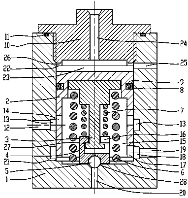
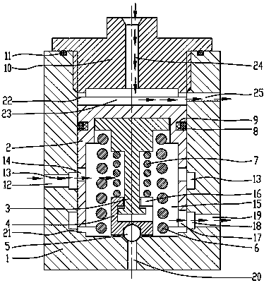
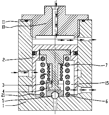
[0028] attached Figure 1-7 It is a specific embodiment of the present invention. This invention is a new type of pressure regulating valve structure, including regulating valve body 1, piston 2, valve joint 10 and valve seat 4. The regulating valve body 1 is provided with a piston 2, and the piston 2 and regulating valve body 1 form a piston air cavity. 15. There is a pressure relief air passage 20 at the bottom of the regulating valve body 1, a valve seat 4 is provided in the corresponding pressure relief passage 20 in the regulating valve body 1, a valve stem 3 is arranged inside the piston 2, and one end of the valve stem 3 is located in the valve seat 4 , the top surface of the other end is pressed against the inner surface of the piston 2 by the spring force of the piston spring 6; the valve seat 4 presses the steel ball 5 against the regulating valve body of the regulating valve body 1 by the spring force of the valve stem spring 7 On the sealing cone surface 28, the r...


PUM


Abstract

The invention belongs to the technical field of diesel oil and natural gas dual fuel injection systems, and particularly relates to a novel pressure regulating valve structure. The novel pressure regulating valve structure comprises a regulating valve body, a piston, a valve joint and a valve seat. The piston is arranged in the regulating valve body. A piston gas cavity is formed by the piston andthe regulating valve body. A pressure relief gas channel is arranged at the bottom of the regulating valve body. The valve seat is arranged at the position, corresponding to the pressure relief gas channel, in the regulating valve body. A valve rod is arranged in the piston. The valve seat presses a steel ball onto a regulating valve body sealing conic face of the regulating valve body through spring force of a valve rod spring. The valve joint is arranged on the regulating valve body and is provided with an oil inlet hole. An oil cavity is formed between the valve joint and the piston. The novel pressure regulating valve structure has the beneficial effects that the structure is simple; the sealing structure is effective and reliable; the problem of serious leaking of current pressure regulating valve products is solved; the machining difficulty is reduced; and arrangement complexity of an oil channel and the gas channel is reduced.

Description

technical field [0001] The invention belongs to the technical field of diesel and natural gas dual-fuel injection systems, and in particular relates to a novel pressure regulating valve structure. Background technique [0002] Currently, medium and heavy-duty vehicles on the market mainly use diesel as fuel, and the combustion efficiency of this type of internal combustion engine is basically lower than 39%. Rail system) matching costs and technical difficulties are gradually increasing, which also brings about an increase in cost. [0003] With the adjustment of the country's energy structure and the improvement of emission requirements, the traditional internal combustion engines that use gasoline and diesel as combustion media will gradually decrease. Natural gas is rich in resources in my country, and it has gradually been used in the automobile market as an alternative fuel to diesel. However, the current natural gas internal combustion engines are all port injection,...

Claims


Application Information

Patent Timeline
Patent Type & Authority Applications(China)
IPC IPC(8): F16K31/122F16K1/42F16K1/48F16K17/20
CPCF16K1/42F16K1/48F16K17/20F16K31/1221Y02T10/30
Inventor 张建明姬广存
Owner 英嘉动力科技无锡有限公司
Learn More