
Pneumatic tire

A technology for pneumatic tires and tires, which is applied to heavy-duty tires, tire parts, tire sidewalls, etc., can solve the problems of increasing rubber volume, increasing tire quality, and deteriorating ride comfort, so as to suppress longitudinal rigidity and improve Cut resistance, effect of inhibiting increase

Active Publication Date: 2012-04-18
SUMITOMO RUBBER IND LTD
View PDF7 Cites 16 Cited by
  • Summary
  • Abstract
  • Description
  • Claims
  • Application Information

AI Technical Summary

Problems solved by technology

[0003] However, since such a protective portion c is continuously provided in the tire circumferential direction, there is a problem of increasing the rubber volume, thereby increasing the tire mass.
In addition, there is a problem that the longitudinal rigidity of the tire is excessively increased due to the protective portion c, and the riding comfort is deteriorated.

Method used


Image

  • Pneumatic tire
  • Pneumatic tire
  • Pneumatic tire

Examples


Embodiment Construction

[0026] Hereinafter, one embodiment of the present invention will be described based on the drawings.

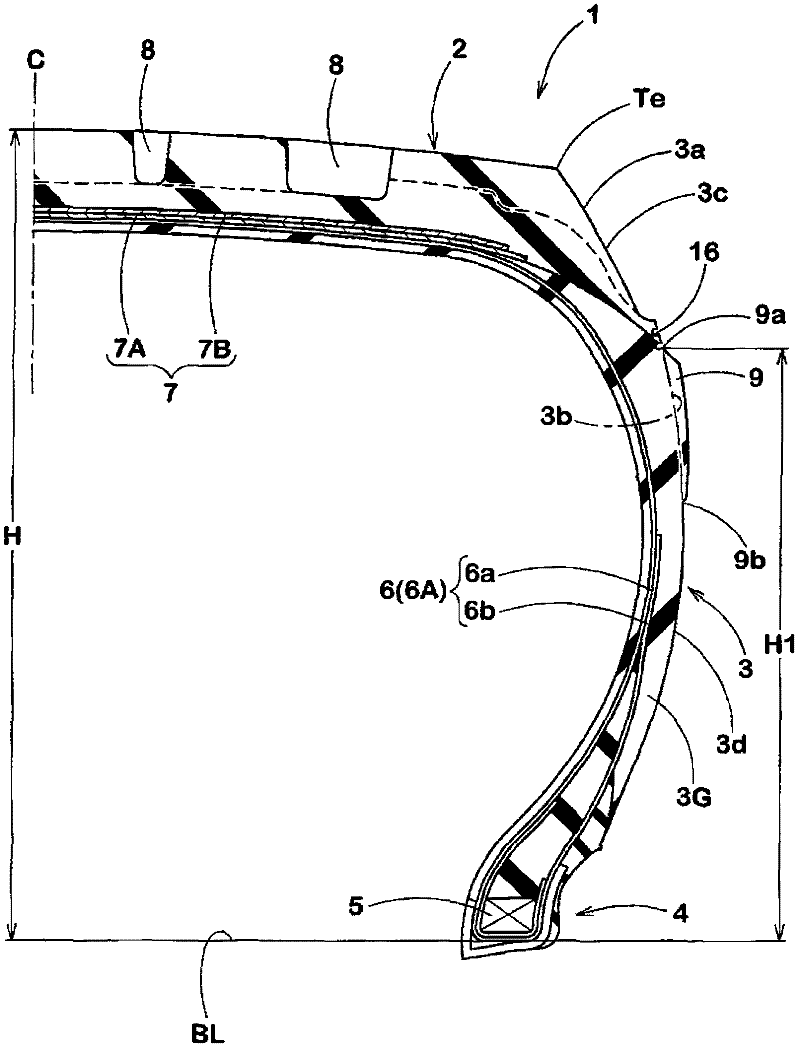
[0027] figure 1 It is a sectional view of a normal state of a pneumatic tire (hereinafter, sometimes simply referred to as "tire") 1 according to this embodiment, and includes a tread portion 2 and a pair of tires extending from both axial ends of the tread portion 2 toward the inside in the tire radial direction. The side portions 3 , and the bead portions 4 arranged at the inner ends in the tire radial direction of the respective side portions 3 . In this specification, "normal state" refers to the normal state of no load in which the tire is assembled to a normal rim (not shown) by a rim and filled with a normal internal pressure. Unless otherwise specified, each part of the tire Dimensions and the like are values ​​measured in this regular state.

[0028] Here, the above-mentioned "regular rim" refers to a rim whose specification is determined for each tire in the spec...


PUM


Abstract

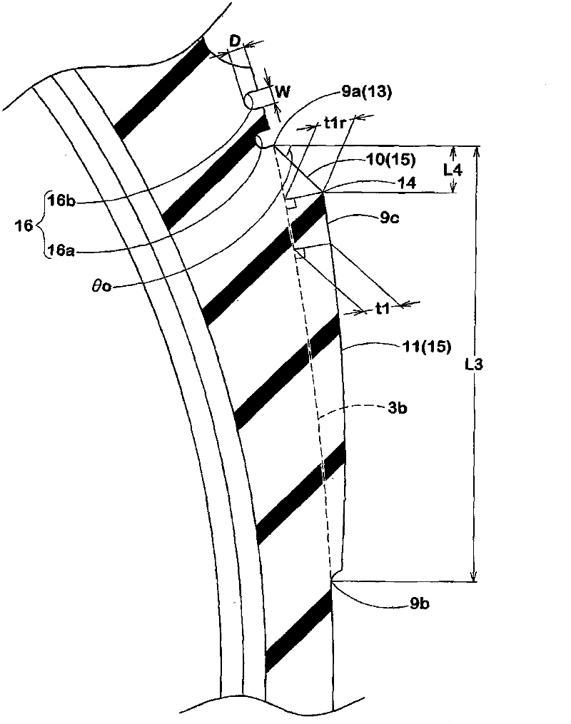
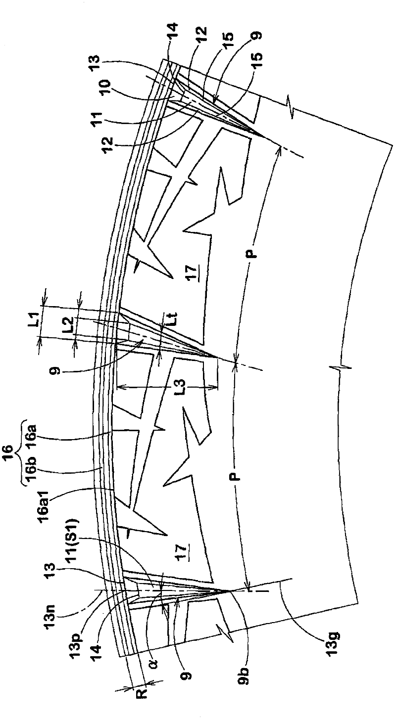
A pneumatic tire comprising a plurality of protector ribs 9 disposed on outer surface 3a of at least one sidewall portion 3 at intervals in the circumferential direction, each protector rib 9 projecting axially outwardly, extending at an angle [alpha] of 5 to 25 DEG with respect to the radial direction, and including outer wall 10 extending from a radially outer edge 13 having a circumferential length L1 of 10 to 25 mm, to maximum projecting portion 14 at which thickness t1 of the rib 9 reaches a maximum, and in a meridian cross section of the tire in a normal loaded state, the outer wall 10 being parallel to flat surface M or extending from the outer edge 13 toward the maximum projecting portion 14 with inclination in a direction away from the flat surface M at an angle of at most 15 DEG with respect to the flat surface M.

Description

technical field [0001] The present invention relates to a pneumatic tire that maintains cut resistance, suppresses an increase in tire mass, and improves ride comfort. Background technique [0002] In pneumatic tires used for vehicles such as four-wheel drive vehicles and trucks that run on poor roads, the sidewalls may collide with sharp stones when running on poor roads, and cuts may occur on the sidewalls. In the past, in order to deal with such problems, such as Figure 7 As shown, a protective portion c protruding outward in the tire axial direction is provided on the outer surface of the sidewall portion a to improve the cut resistance. [0003] However, since such a protective portion c is continuously provided in the tire circumferential direction, there is a problem of increasing the rubber volume, thereby increasing the tire mass. In addition, there is a problem that the longitudinal rigidity of the tire is excessively increased due to the protective portion c, an...

Claims


Application Information

Patent Timeline
Patent Type & Authority Applications(China)
IPC IPC(8): B60C13/02
CPCB60C13/002B60C13/02B60C13/00B60C2200/06
Inventor 黑泽弘之
Owner SUMITOMO RUBBER IND LTD
Learn More