
Shaft system for use in a chuck of a winding head

A winding head and chuck technology, which is used in the field of hollow shafts or hollow shafts, can solve the problems of short grease life of roller bearings, expensive drive shafts or driven shafts, etc., and achieve improved bearing structure, low cost effect

Inactive Publication Date: 2012-04-11
SCHAEFFLER TECH AG & CO KG
View PDF3 Cites 4 Cited by
  • Summary
  • Abstract
  • Description
  • Claims
  • Application Information

AI Technical Summary

Problems solved by technology

In contrast, usable roller bearings have a too short grease service life and must be replaced after a short operating time
In addition, the application of spindle bearings to support the drive shaft or driven shaft is relatively expensive

Method used


Image

  • Shaft system for use in a chuck of a winding head
  • Shaft system for use in a chuck of a winding head
  • Shaft system for use in a chuck of a winding head

Examples


Embodiment Construction

[0026] figure 1 A so-called nested shaft system 100 is shown in a schematic view with a central output shaft 1 , which is fixed in rotation at one end of the output shaft with an output element 2 , for example a bushing. connect. Furthermore, the shaft system 100 has a stationary spindle 3 of the bearing bush type, which is arranged coaxially with the driven shaft 1 and accommodates the driven shaft 1 at least partially coaxially in the axial direction.

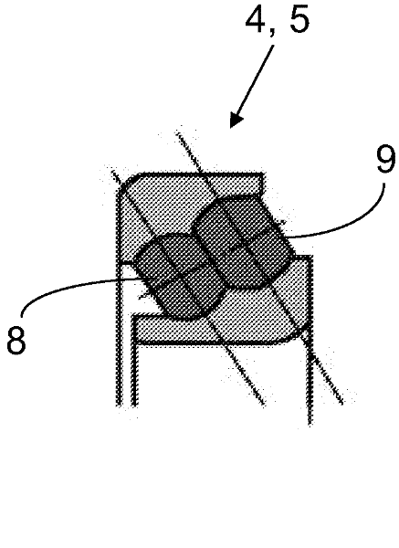
[0027] For supporting the driven shaft 1, the shaft system 100 has at least two rolling bearings 4, 5, which are arranged at a distance from each other in the axial direction, are supported with their outer circumference on the spindle or carrier bushing 3 and with their The inner circumference carries the driven shaft 1. The carrier bushing 3 is supported radially outward via an elastic damping element 6 on a further torsionally fixed spindle 7 arranged coaxially with the output shaft 1 . The torsionally fixed mandrel 7 i...


PUM


Abstract

The invention relates to a shaft system (100) for use in a chuck (110) of a winding head (120) for winding, for example, synthetic threads, comprising at least one input or output shaft (1) and at least one axis (3) or another shaft, which (3) is arranged coaxially to the input or output shaft (1), wherein at least one of said components (1, 3) is designed as a hollow shaft or hollow axis (3) and the other component (1) is received therein at least partially and is supported with respect to the hollow shaft or hollow axis (3) by means of at least one bearing (4, 5). According to the invention, the bearing is designed as a ball roller bearing (4, 5), which is arranged radially inside on the outer circumference of the rotatable shaft (1) and radially outside on the inner circumference of the stationary axis (3).

Description

technical field [0001] The invention relates to a shaft system for use in a chuck of a winding head with at least one drive shaft or driven shaft and at least one hub arranged coaxially with the drive shaft or driven shaft Shafts or other shafts, wherein at least one of these components is configured as a hollow shaft or hollow mandrel, and the other component is at least partially accommodated in the hollow shaft or hollow mandrel and relative to the hollow shaft or hollow mandrel by means of at least A bearing support. Furthermore, the invention relates to a chuck with such a shaft system for a winder of a spinning machine as well as a winder of a spinning machine and a spinning device for synthetic fibres. Background technique [0002] Shaft systems of the type described here, for example used in winder chucks of spinning machines for synthetic fibres, generally have grooved ball bearings, roller bearings and / or or spindle bearings. A shaft system of the same type is k...

Claims


Application Information

Patent Timeline
Patent Type & Authority Applications(China)
IPC IPC(8): B65H54/547
CPCB65H54/547
Inventor 乌韦・朱津格马丁・施赖伯乌尔里克・茨维尔斯约亨・阿德勒
Owner SCHAEFFLER TECH AG & CO KG
Learn More