
Networking method of wireless grid sensor based on link stability estimation

A sensor network and stability technology, applied in wireless communication, network topology, network planning, etc., can solve problems such as low network throughput, high network delay, and high protocol overhead

Inactive Publication Date: 2012-04-11
HARBIN INST OF TECH
View PDF4 Cites 8 Cited by
  • Summary
  • Abstract
  • Description
  • Claims
  • Application Information

AI Technical Summary

Problems solved by technology

[0011] The purpose of the present invention is to solve the problems of low network throughput, high network delay and high protocol overhead caused by the fact that the original sensor network networking technology cannot use the geographical location information of the local node itself for link estimation, and proposes a A Networking Method for Wireless Grid Sensor Networks Based on Link Stability Estimation

Method used


Image

  • Networking method of wireless grid sensor based on link stability estimation
  • Networking method of wireless grid sensor based on link stability estimation
  • Networking method of wireless grid sensor based on link stability estimation

Examples


specific Embodiment approach 1

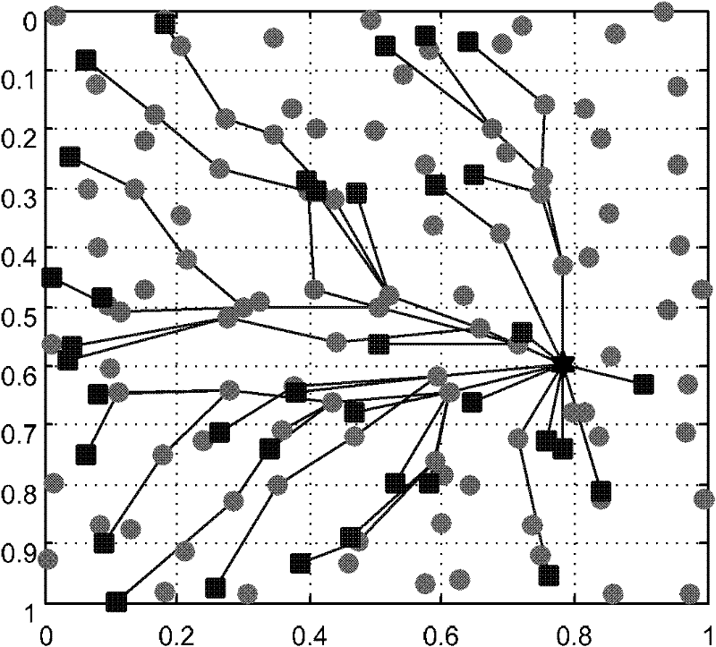
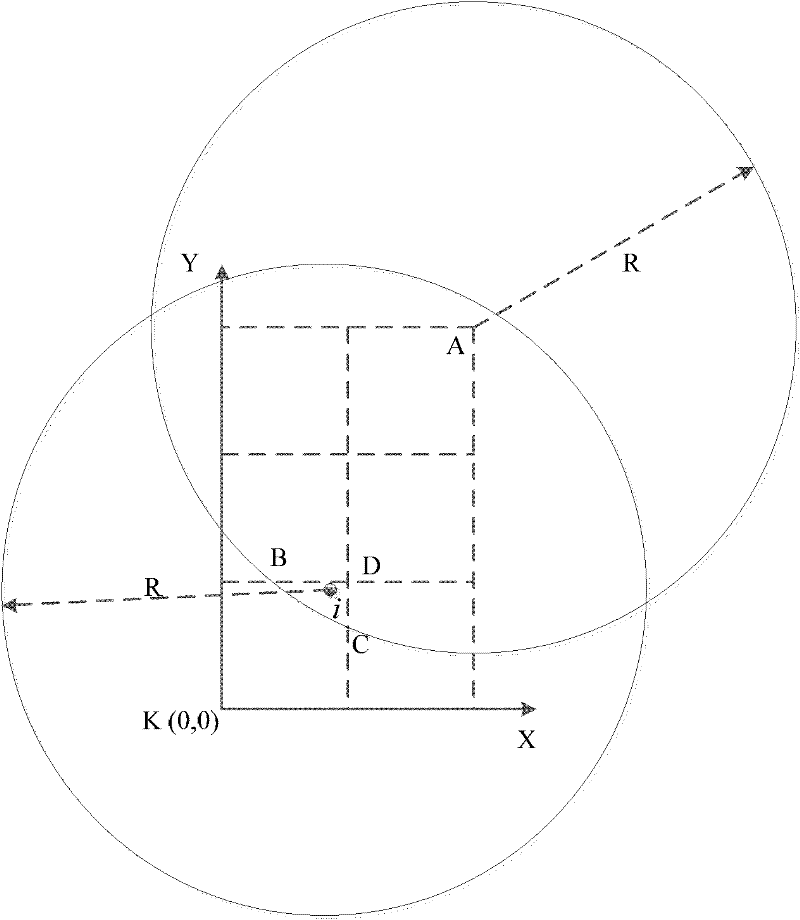
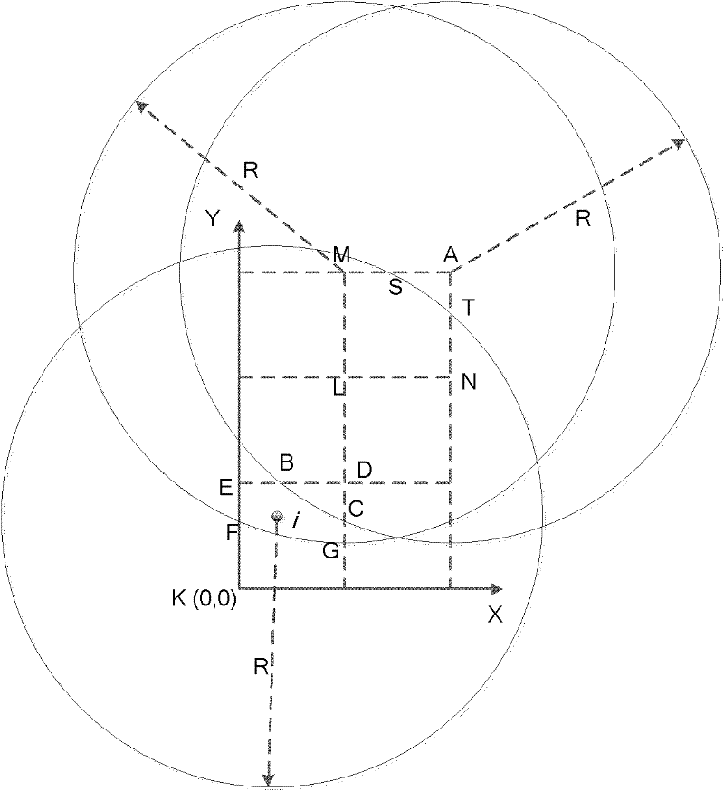
[0071] Specific implementation mode one: the following combination figure 1 and figure 2 Describe this embodiment, the steps of a wireless grid sensor network networking method based on link stability estimation described in this embodiment are:

[0072] Step 1. Divide the wireless sensor network into grids. There are several sensor nodes in each grid. During the data transmission process, in the same grid, at any time, only one sensor node acts as a relay node;

[0073] Step 2. The central node configures the geometric coordinates of the network, the subnet ID, the coordinates of the central node and its ID, the number of grids in the vertical direction m and the number of grids in the horizontal direction n through flood broadcasting;

[0074] Step 3. Each relay node that receives the configuration packet for the first time calculates the horizontal length H and the vertical length L of the network according to the network parameters, records the configuration information,...

specific Embodiment approach 2

[0104] Specific implementation mode two: the following combination figure 1 and figure 2 Describe this embodiment. This embodiment is a further description of a wireless grid sensor network networking method based on link stability estimation described in Embodiment 1.

[0105] The sensor nodes described above are only responsible for data collection and data transmission, and do not provide relay services for other nodes.

specific Embodiment approach 3

[0106] Specific implementation mode three: the following combination figure 1 and figure 2 Describe this embodiment. This embodiment is a further description of a wireless grid sensor network networking method based on link stability estimation described in Embodiment 1.

[0107] The relay node can be a specially designed node or a node selected from sensor nodes.


PUM


Abstract

The invention relates to a networking method of a wireless grid sensor based on link stability estimation, in particular to a networking method of a wireless sensor network to solve the problems that the network throughput is low, the network time delay is high and the protocol expenditure is high caused by that the original sensor networking method cannot utilize geographic location information to carry out link estimation by local nodes. The wireless sensor network is divided into grids; when a data group of one sensing node or a relay node needs to be sent to a center node, a sending direction of the group is initially selected according to relative position information between the sensing node or the relay node and the center node and all the alternative relay nodes are listed; and link stability information of all the alternative relay nodes in the direction is estimated by estimating the link stability information of a sending node and the relay nodes in the grids by the sending node according to the relative position information between the sending node and the adjacent grids in the selected direction. The method provided by the invention is used for establishing a network.

Description

technical field [0001] The invention relates to a wireless sensor network networking method. Background technique [0002] The background technology adopted in the application of the present invention can be summarized as the following points: 1) multi-hop wireless relay technology; 2) low-overhead network transmission technology; 3) fault-tolerant technology based on link stability; 4) ID-based addressing technology ; 5) Static network efficient networking technology. [0003] Nodes in wireless sensor networks are usually composed of wireless transceiver devices with very limited communication performance due to cost and volume constraints. These devices transmit the various monitoring signals collected to the remote central node by means of multi-hop relay transmission, so as to jointly complete the monitoring task of a specific environmental parameter. Common monitoring objects include air pollutants and humidity. , temperature, and the electromagnetic spectrum. Wirele...

Claims


Application Information

Patent Timeline
IPC IPC(8): H04W16/06H04W84/18
Inventor 吴少川高玉龙白旭张文彬张佳岩李文昊刘红芹
Owner HARBIN INST OF TECH
Learn More