Joint estimation method and system for carrier frequency offset, frame head phase position and fine symbol timing

A carrier frequency offset and joint estimation technology, which is applied to the joint estimation of frame header phase and fine timing, and the field of carrier frequency offset of receivers, can solve the problems of small frequency offset estimation range, large amount of frequency sweep calculation, and reduced calculation amount. , to achieve the effect of fast carrier frequency offset estimation

Inactive Publication Date: 2012-04-11
TIMI TECH
View PDF6 Cites 10 Cited by
  • Summary
  • Abstract
  • Description
  • Claims
  • Application Information

AI Technical Summary

Problems solved by technology

However, the frame header phase identification is very sensitive to the residual carrier frequency offset. The usual carrier frequency offset estimation method uses the same part of the two sections before and after to do sliding autocorrelation, and the frequency offset estimation range is small; the frequency sweep cross-correlation method uses pre-stored The local PN sequence in the receiver performs sliding cross-correlation with the PN sequence in the received signal. When the frequency offset is large, the calculation amount of the frequency sweep is large. When the scale setting of the frequency sweep is large, the calculation amount is reduced, but the estimation performance will be deteriorated.

Method used


Image

  • Joint estimation method and system for carrier frequency offset, frame head phase position and fine symbol timing
  • Joint estimation method and system for carrier frequency offset, frame head phase position and fine symbol timing
  • Joint estimation method and system for carrier frequency offset, frame head phase position and fine symbol timing

Examples


Embodiment Construction

[0049] Embodiments of the present invention are described in detail below, examples of which are shown in the drawings, wherein the same or similar reference numerals designate the same or similar elements or elements having the same or similar functions throughout. The description is exemplary, and is only used to explain the present invention, but not to be construed as a limitation of the present invention.

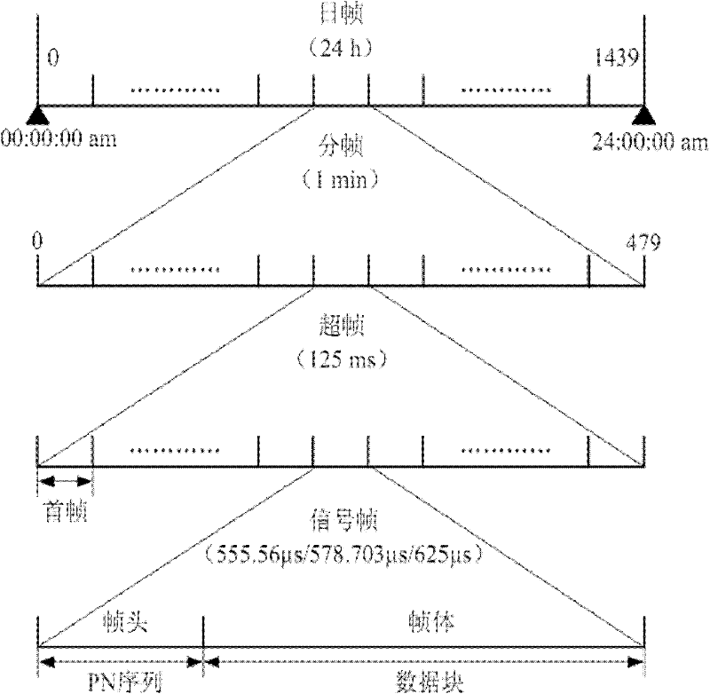
[0050] Preferred embodiments of the present invention will be described in detail below in conjunction with the accompanying drawings. The digital terrestrial television standard DMB-TH adopts a hierarchical frame structure, which is periodic and can be synchronized with absolute time. Such as figure 1 Shown is a schematic diagram of the hierarchical frame structure of DMB-TH. The hierarchical frame structure includes four layers, which are: daily frame, sub-frame, super frame, and signal frame from top to bottom. The signal frame is the basic unit of the frame struc...


PUM


Abstract

The invention provides a joint estimation method for carrier frequency offset, frame head phase position and fine symbol timing. The method comprises the following steps of: estimating integral frequency offset according to a received signal; performing integral frequency offset compensation according to the integral frequency offset; performing fractional frequency offset estimation; adding the integral frequency offset with the fractional frequency offset to obtain total carrier frequency offset, and performing total carrier frequency offset compensation according to the total carrier frequency offset; performing frame head phase identification on a first frame according to the received signal; and estimating the position fine symbol timing according to the frame head phase of the first frame. The invention further provides a system which corresponds to the method. According to the method and the system, carrier frequency offset estimation, frame head phase position and fine symbol timing can be rapidly realized on the premise of ensuring the demodulating performance of a receiver.

Description

technical field [0001] The invention relates to the technical field of terrestrial digital television, in particular to a method and system for joint estimation of carrier frequency offset, frame header phase and fine timing of a receiver. Background technique [0002] The digital terrestrial TV standard DMB-TH adopts a four-layer hierarchical frame structure, which are: daily frame, sub-frame, super frame and signal frame from top to bottom. It is periodic and can be synchronized with absolute time. [0003] The signal frame is the basic unit of the frame structure, the super frame is defined as a group of signal frames, the sub-frame is defined as a group of super frames, corresponding to 1 minute, and the daily frame is a group of frames, corresponding to 24 hours. The signal frame includes frame header and frame body. The frame header is filled with PN sequence, and the frame body can be data in single-carrier mode or multi-carrier mode, and the data length is 3780 poi...

Claims


Application Information

Patent Timeline
Patent Type & Authority Applications(China)
IPC IPC(8): H04B1/7105H04L25/03H04L25/02
Inventor 王静葛啟宏刘斌彬
Owner TIMI TECH
Why Eureka
Try Eureka