Industrial machine

A technology of industrial machines and feeders, which is applied in the direction of program control and safety arrangements in instruments, sequence/logic controllers, etc., to achieve the effect of promoting energy saving and avoiding waste release

Active Publication Date: 2012-04-11
MITUTOYO CORP
View PDF4 Cites 0 Cited by
  • Summary
  • Abstract
  • Description
  • Claims
  • Application Information

AI Technical Summary

Problems solved by technology

However, there are also cases where the machine is only used for a short period of time, for example around 2-5 hours per day

Method used


Image

  • Industrial machine
  • Industrial machine
  • Industrial machine

Examples


Embodiment Construction

[0015] The details shown here are by way of example only and for illustrative purposes only of discussing embodiments of the invention, and are set forth in order to provide what is believed to be the most useful and understandable description of the principles and aspects of the invention. In this regard, no attempt has been made to show structural details of the invention in more detail than is required for a fundamental understanding of the invention, but rather, the illustrations, taken in conjunction with the drawings, will make clear to the skilled artisan how the invention may actually be implemented in a form Obvious to a technician.

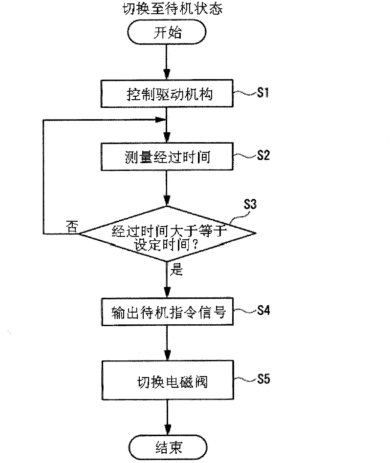
[0016] Embodiments of the present invention will be described below based on the drawings. figure 1 is a diagram showing a schematic configuration of a three-dimensional measuring machine which is an industrial machine according to an embodiment of the present invention. figure 2 It is a figure which shows the air conditioner group pro...


PUM


Abstract

A three-dimensional measuring machine (industrial machine) includes an air supplier supplying air; a drive mechanism driven by the air supplied from the air supplier; an electromagnetic valve provided inside an air regulator set to open and close an air supply passage inside the air regulator set, the air regulator set introducing the air from the air supplier to the drive mechanism; and a motion controller controlling the electromagnetic valve to block the air supply passage when a time since the drive mechanism stopped operation reaches a preset time.

Description

technical field [0001] The invention relates to an industrial machine with an air-driven drive mechanism. Background technique [0002] Conventionally, industrial machines such as three-dimensional measuring machines are known in which a moving mechanism is driven using air pressure of air supplied from an air supplier (see, for example, Japanese Patent Laid-Open No. 2003-148581). In the three-dimensional measuring machine disclosed in Japanese Patent Laid-Open No. 2003-148581, the moving mechanism is moved by a driving force supplied from a driving source. In this case, driving resistance is reduced by sucking air from an air supplier to an air bearing. In this measuring machine, after the probe is moved to a desired position, the measuring machine enters a standby state. In the standby state, when the user operates the three-dimensional measuring machine, the air from the air supply is continuously released to the moving mechanism, so that the three-dimensional measuring...

Claims


Application Information

Patent Timeline
Patent Type & Authority Applications(China)
IPC IPC(8): G05B19/04
CPCG05B19/44G05B9/02
Inventor 福田满河原井一晃水上一己大坪圣一
Owner MITUTOYO CORP
Why Eureka
Try Eureka