
Dynamic monitoring system device for tailing dam body by three-dimensional laser scanning

A three-dimensional laser, dynamic monitoring technology, applied in measuring devices, measuring instruments, mapping and navigation, etc., can solve the problems of low cost, fast single scanning speed, high measurement accuracy, and achieve high reliability.

Inactive Publication Date: 2012-04-11
BEIHANG UNIV
View PDF4 Cites 19 Cited by
  • Summary
  • Abstract
  • Description
  • Claims
  • Application Information

AI Technical Summary

Problems solved by technology

[0004] The technical problem solved by the present invention is to overcome the shortcomings of the existing online monitoring technology, provide a set of non-contact dynamic online monitoring device for three-dimensional laser scanning tailings dam body, realize non-contact online timing monitoring, fast single scanning speed, and high measurement accuracy high and low cost; the invention effectively meets the national requirements on safe production, and the device is suitable for tailings dam monitoring in different scenarios

Method used


Image

  • Dynamic monitoring system device for tailing dam body by three-dimensional laser scanning
  • Dynamic monitoring system device for tailing dam body by three-dimensional laser scanning
  • Dynamic monitoring system device for tailing dam body by three-dimensional laser scanning

Examples


Embodiment Construction

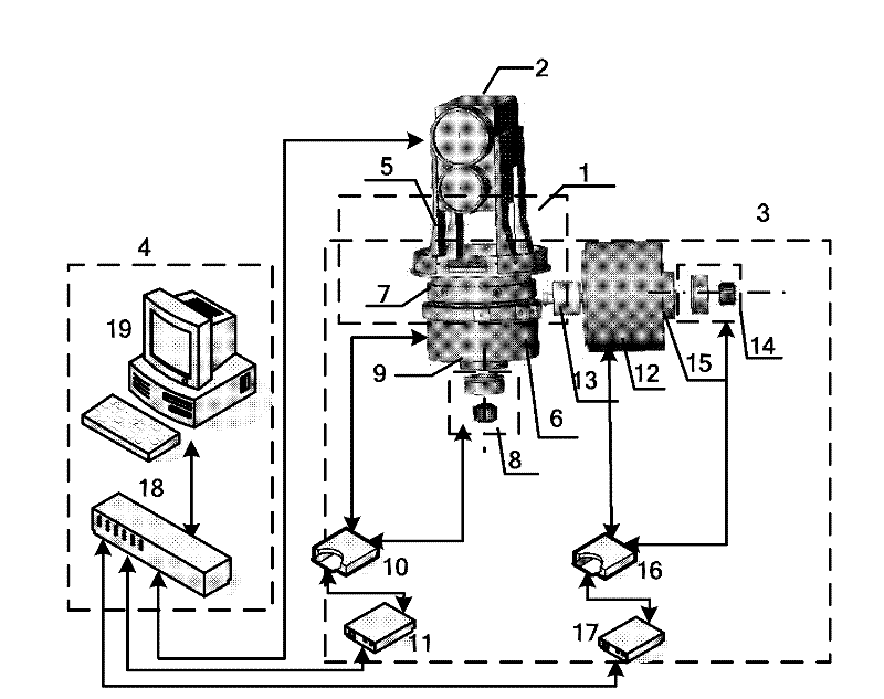
[0045] Such as figure 1 As shown, the three-dimensional laser scanning tailings dam dynamic monitoring system device of the present invention includes: a mechanical unit 1, a laser data acquisition unit 2, a control drive and feedback unit 3, a communication and a host computer unit 4, wherein

[0046] The mechanical unit 1 is used to connect the laser data acquisition unit 2 with the horizontal direction motor 6 and the vertical direction motor 12 to realize the horizontal and vertical direction scanning of the laser data acquisition unit 2; The direction motor moves synchronously with the fixation of the horizontal resolver connection device 9 , and the vertical resolver 14 and the vertical motor 12 move synchronously with the fixation of the vertical motor and the vertical resolver connection device 15 .

[0047] The laser data acquisition unit 2 can obtain the polar radius information of the ground object point scene in real time. Driven by the horizontal direction motor ...


PUM

PropertyMeasurementUnit
Poweraaaaaaaaaa
Electric currentaaaaaaaaaa
Poweraaaaaaaaaa

Abstract

The invention discloses a dynamic monitoring system device for a tailing dam body by three-dimensional laser scanning. The dynamic monitoring system device mainly comprises a mechanical unit, a laser data acquisition unit, a control driving and feedback unit, and a communication and upper computer unit. In the device, the laser data acquisition unit is used for acquiring scene polar radius information of the surface of the tailing dam body; the control driving and feedback unit is used for driving the laser data acquisition unit to rotate in the horizontal dimension and vertical dimension, toscan the large scene on the surface of the tailing dam body at a constant speed and to acquire angle information in the horizontal dimension and the vertical dimension in real time; the communicationand upper computer unit is used for transmitting the acquired distance information and the acquired angle information to an upper computer through a high-speed data acquisition card; and software of the upper computer is used for processing the scene polar radius and the rotation angle information in the horizontal dimension and the vertical dimension to recover a real three-dimensional image of the scene, building a tailing dam body standard point cloud model in an ideal state, and storing the model into a database as an intelligent monitoring comparison template. During dynamic scanning of the device, qualitative and quantitative estimation for unexpected disasters is realized by using a dynamic monitoring algorithm through comparison with the template; operators and managers can immediately start corresponding emergency plans to avoid further expansion of the disasters.

Description

technical field [0001] The invention relates to a non-contact measurement technology, in particular to a non-contact dynamic on-line monitoring system device for three-dimensional laser scanning tailings dam body. Background technique [0002] In the "Twelfth Five-Year Plan" development plan for national safety production, there are clear requirements for the installation of online monitoring system devices for third-class and above tailings ponds within a limited period. The 3D laser scanning tailings dam dynamic monitoring system device is a typical prototype of the tailings dam on-line monitoring system, which meets the needs of the era for safe and steady development, and is of great significance to the protection of the country and people's life and property safety. [0003] Foreign countries have formed a monitoring and early warning system that includes functions such as on-site real-time data collection, comprehensive analysis of data, and safety alarms for tailings ...

Claims


Application Information

Patent Timeline
IPC IPC(8): G01C15/00
Inventor 胡少兴
Owner BEIHANG UNIV
Learn More