
Antenna array calibration method and device in Orthogonal Frequency Division Multiplexing (OFDM) system

An antenna calibration and antenna technology, applied in the field of antenna array calibration, can solve the problems of array antenna calibration accuracy calibration method complexity and other issues

Inactive Publication Date: 2012-04-04
BEIJING JIAOTONG UNIV
View PDF5 Cites 46 Cited by
  • Summary
  • Abstract
  • Description
  • Claims
  • Application Information

AI Technical Summary

Problems solved by technology

[0007] The object of the present invention is to avoid the deficiencies of the above prior art and provide a method and device for calibrating antenna arrays in an OFDM system to solve the problems of the accuracy of calibrating array antennas and the complexity of calibrating methods in LTE systems

Method used


Image

  • Antenna array calibration method and device in Orthogonal Frequency Division Multiplexing (OFDM) system
  • Antenna array calibration method and device in Orthogonal Frequency Division Multiplexing (OFDM) system
  • Antenna array calibration method and device in Orthogonal Frequency Division Multiplexing (OFDM) system

Examples


Embodiment 1

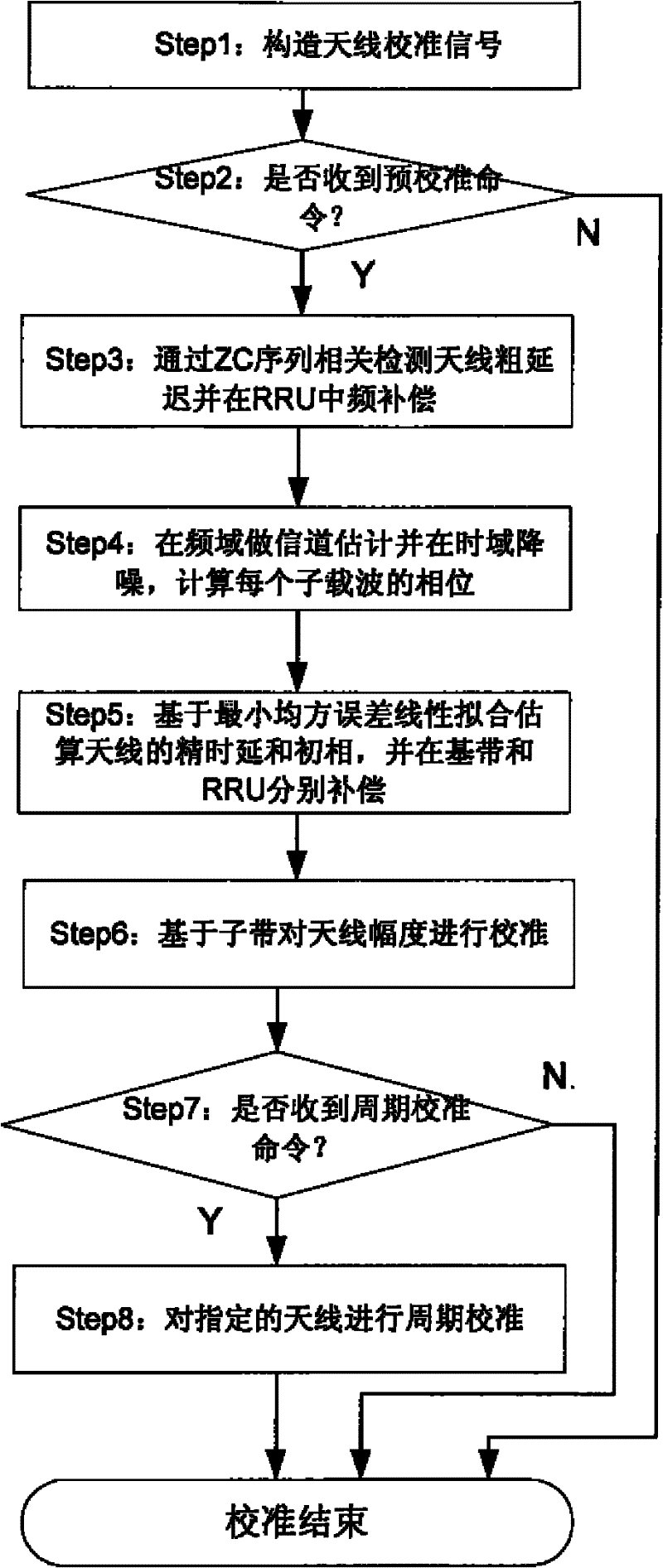
[0045] figure 1 It is a schematic flowchart of the application of the method and device for calibrating the array antenna of the present invention in the TDD-LTE system. Before calibration, construct a ZC sequence with a length of 1024, 0≤n≤1023, u is the ZC sequence index. The calibration sequence can also use m-sequence or other sequences with good autocorrelation properties. will x u (n) is mapped to the system subcarrier x(k),

[0046] according to figure 2 As shown to generate a calibration signal in the time domain, the front and rear CPs are taken to be sufficient to cover the possible maximum delay value, for example, 256. It can also roughly estimate the delay of the received signal relative to the transmitted signal according to the system design, and adjust the receiving time of the received signal accordingly. In order to better explain the present invention, we take the commonly used LTE configuration, 20M bandwidth, eight-antenna array, and 30.72M baseban...


PUM


Abstract

The invention relates to antenna array calibration method and device in an Orthogonal Frequency Division Multiplexing (OFDM) system. The method disclosed by the invention comprises a pre-calibration step and a periodical calibration step to antennas, wherein the pre-calibration step is mainly used for acquiring compensation coefficients in a transmission direction and a reception direction of antenna units with respect to an antenna calibration unit; and the periodical calibration step performs transmission calibration and reception calibration to each antenna unit in quasi real-time according to a preset period. The method and the device disclosed by the invention can realize real-time and high-precision calibration of consistency of phases of a reception channel and a transmission channel of a Long Term Evolution (LTE) system, through common compensation to time delay and the phases through a Building Baseband Unit (BBU) and a Radio Remote Unit (RRU), can guarantee high consistency of phases of an air interface sending signal and a BBU reception signal of an antenna array, and is particularly suitable for a communication system which has high demand on consistency of antennas, for example, a Time Division Duplex (TDD)-LTE, etc..

Description

technical field [0001] The present invention relates to wireless communication technology, in particular to an antenna array calibration method and device in an OFDM system. Background technique [0002] In the LTE system (Long Term Evolution referred to as LTE), in order to increase the coverage of the cell, reduce the interference between users in the cell and between cells, and increase the throughput of users at the edge of the cell, an array antenna is introduced on the base station (eNodeB) side. Beamforming technology. Array antenna beamforming refers to the formation of an antenna array by multiple antenna units according to a certain geometric shape. By adjusting the weighted amplitude and phase of each array signal to change the antenna pattern of the array, the signal power expected to be received by the user is maximized. Undesired users outside the beam coverage experience minimal interference. The premise of the application of array antenna beamforming techno...

Claims


Application Information

Patent Timeline
IPC IPC(8): H04B7/06H04B7/08H04L27/26
Inventor 余少伟裴丽刘超
Owner BEIJING JIAOTONG UNIV
Learn More