


Quick Research
Generate reliable direction feasibility study reports for your R&D in just a few steps.

Technical Q&A
Discover and master advanced knowledge NOW. Basics, ideas, possibilities, all at once.

Find Solutions
As an expert in R&D theories, this can generate solutions to your technical problems instantly.

Evaluate Feasibility
Analyze your overall solution with one click, know your potential R&D risks in advance.

Monitor Landscape
Get weekly tech updates, stay abreast of the latest tech innovations and key insights.
Dual-bearing reel drag sound producing device
A sounding device and reel technology, applied in fishing reels, fishing, applications, etc., can solve the problems of longer handle shaft length and longer axial length of double bearing reels, etc. Smooth action, avoid stuck effect
- Summary
- Abstract
- Description
- Claims
- Application Information
AI Technical Summary
Problems solved by technology
Method used
Image

Examples
no. 1 approach
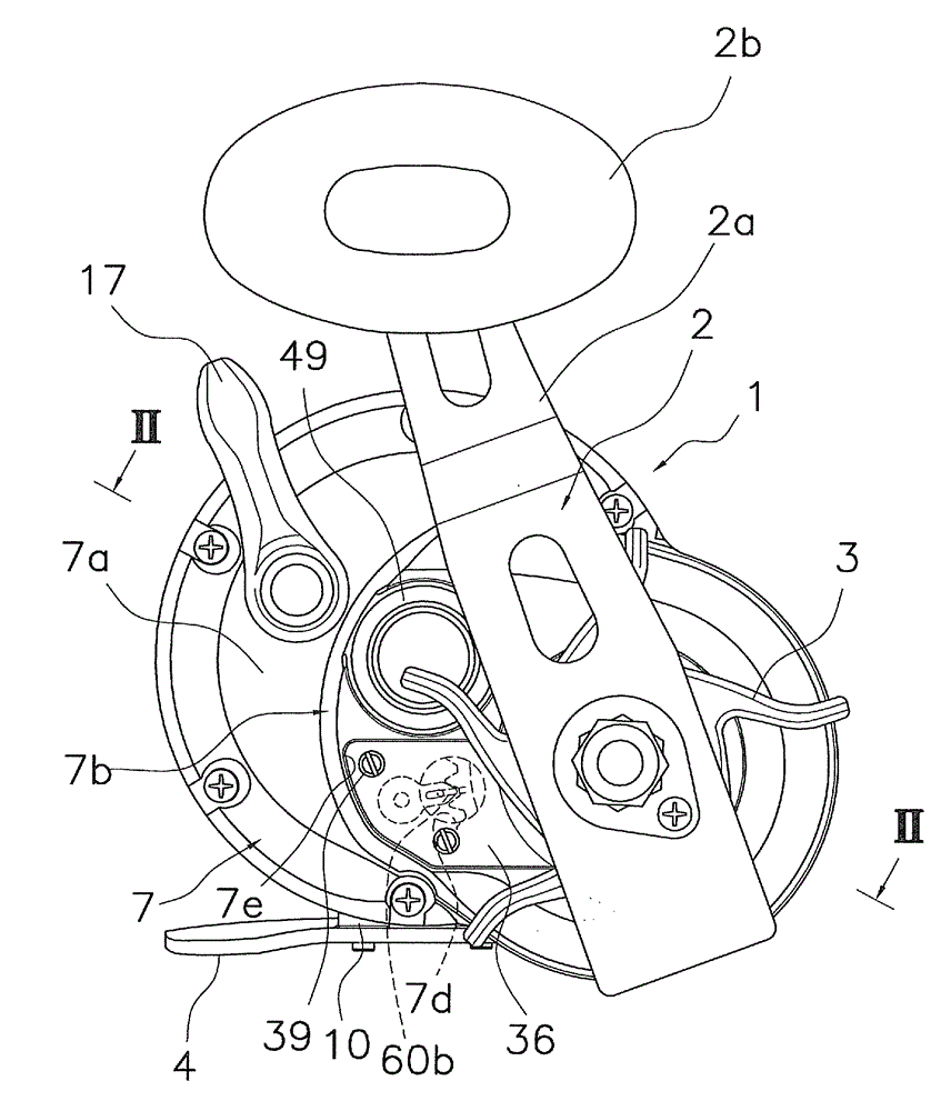
[0064] exist figure 1 and figure 2 Among them, the double-bearing reel employing one embodiment of the present invention is a circular double-bearing reel used for lure casting fishing, jigging, and the like. The double-bearing reel includes: a reel main body 1; a handle 2 for rotating a spool disposed on the side of the reel main body 1; and a spool rotatably mounted inside the reel main body 1 12.
[0065] In addition, front, rear, left, and right mentioned in the following description mean the direction in which the fishing line is released when the double-bearing reel is attached to the fishing rod, and left and right are shown when the double-bearing reel is viewed from the rear.
[0066] The handle 2 is a single-handle type, and has a plate-shaped arm portion 2a and a handle 2b rotatably attached to the end of the arm portion 2a. Such as figure 2 As shown, the arm portion 2 a is attached to the end of the handle shaft 30 so as to be integrally rotatable with the ha...
no. 2 approach
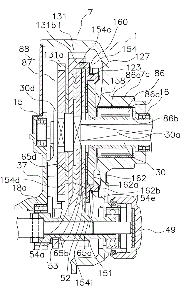
[0113] In the second embodiment, the configurations of the main gear 131 of the gear mechanism 119 , the first drag washer 151 of the drag mechanism 123 , and the rotating member 154 of the drag generating mechanism 127 are different from those of the first embodiment. In addition, only the parts different from the first embodiment will be described below.
[0114] like Figure 6 As shown, a circular housing recess 131 a for housing the drag mechanism 123 is formed on the right side of the main gear 131 . A plurality of (for example, four) first engaging recesses 131b are formed on the inner peripheral surface of the receiving recess 131a, and the first engaging recesses 131b are approximately recessed into a semicircle for integrally rotating with the rotating member. 154 snaps. A plurality of (for example, two) second engaging recesses (not shown) having the same structure as the first embodiment are formed between the two engaging recesses 131b.
[0115] The diameter of ...
PUM
 Abstract
Description
Claims
Application Information
 - R&D Engineer
- R&D Manager
- IP Professional
- Industry Leading Data Capabilities
- Powerful AI technology
- Patent DNA Extraction
Browse by: Latest US Patents, China's latest patents, Technical Efficacy Thesaurus, Application Domain, Technology Topic, Popular Technical Reports.
© 2024 PatSnap. All rights reserved.Legal|Privacy policy|Modern Slavery Act Transparency Statement|Sitemap|About US| Contact US: help@patsnap.com