


Quick Research
Generate reliable direction feasibility study reports for your R&D in just a few steps.

Technical Q&A
Discover and master advanced knowledge NOW. Basics, ideas, possibilities, all at once.

Find Solutions
As an expert in R&D theories, this can generate solutions to your technical problems instantly.

Evaluate Feasibility
Analyze your overall solution with one click, know your potential R&D risks in advance.

Monitor Landscape
Get weekly tech updates, stay abreast of the latest tech innovations and key insights.
Hydrogen generation device and fuel cell system equipped with same
A generation device and generator technology, which is applied in fuel cells, fuel cell additives, hydrogen/syngas production, etc., can solve the problems of hydrogen generation, inability to continue to use fuel cells to generate electricity and heat, etc., and achieve pressure damage reduced effect
- Summary
- Abstract
- Description
- Claims
- Application Information
AI Technical Summary
Problems solved by technology
Method used
Image

Examples
Embodiment approach 1
[0066] Next, a specific configuration example and operation example of the hydrogen generator according to Embodiment 1 of the present invention will be described with reference to the drawings.
[0067] However, the following detailed description merely exemplifies the features of each hydrogen generator listed at the beginning of the column of "Detailed Embodiments". For example, the following specific examples will be described by attaching appropriate reference signs to the same technical terms as those used to designate the above-mentioned hydrogen generating devices. In this case, the relevant specific devices are the above-mentioned hydrogen generating devices corresponding thereto. An example of structural elements.
[0068] Therefore, the characteristics of each of the hydrogen generators described above are not limited to the specific description below.
[0069] [Structure Example of Hydrogen Generator]
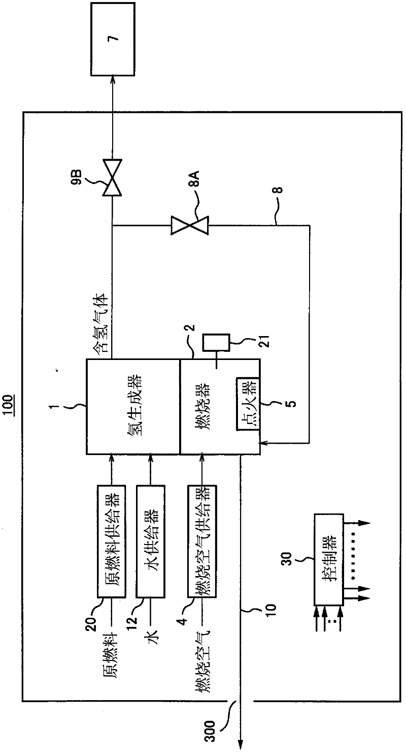
[0070] figure 1 It is a block diagram showing a configurat...
Embodiment approach 2
[0131] Next, a specific configuration example and operation example of the hydrogen generator according to Embodiment 2 of the present invention will be described with reference to the drawings.
[0132] However, the following detailed description merely exemplifies the features of each hydrogen generator listed at the beginning of the column of "Detailed Embodiments". For example, the following specific examples will be described by attaching appropriate reference signs to the same technical terms as those used to designate the above-mentioned hydrogen generating devices. In this case, the relevant specific devices are the above-mentioned hydrogen generating devices corresponding thereto. An example of structural elements.
[0133] Therefore, the characteristics of each of the hydrogen generators described above are not limited to the specific description below.
[0134] [Structure Example of Hydrogen Generator]
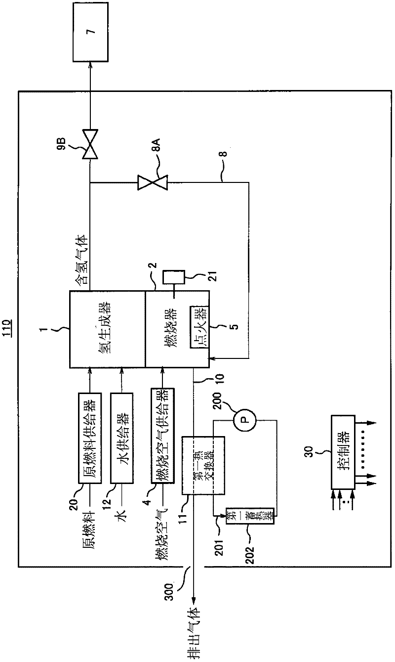
[0135] figure 2 It is a block diagram showing a configurat...
Embodiment approach 3
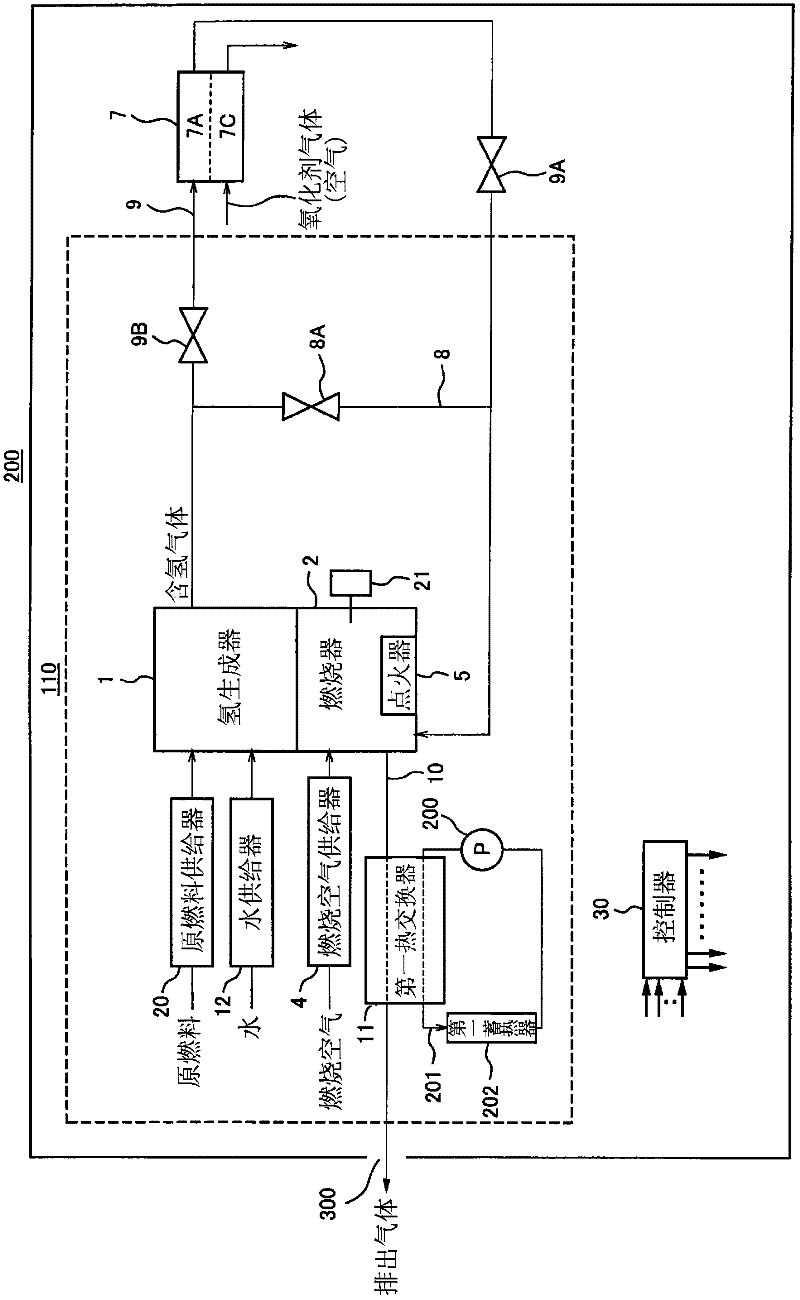
[0149] image 3 It is a block diagram showing a configuration example of a fuel cell system according to Embodiment 3 of the present invention.
[0150] exist image 3 Herein, the same components as those of the hydrogen generator 110 according to Embodiment 2 are given the same reference numerals, and a detailed description of the components will be omitted.
[0151] like image 3 As shown, the fuel cell system of this embodiment uses a fuel cell as the hydrogen utilization device 7, and the fuel cell system further includes: a second gas flow path 9 through which the gas sent from the hydrogen generator 1 passes. An anode gas flow path 7A of the fuel cell 7 is supplied to the burner 2 ; and a second gas on-off valve 9A that communicates / blocks the second gas flow path 9 .
[0152] In the fuel cell system according to the present embodiment, the supply of combustion fuel to the combustor 2 in the start-up process is performed as follows, for example.
[0153] As a first s...
PUM
 Abstract
Description
Claims
Application Information
 - R&D Engineer
- R&D Manager
- IP Professional
- Industry Leading Data Capabilities
- Powerful AI technology
- Patent DNA Extraction
Browse by: Latest US Patents, China's latest patents, Technical Efficacy Thesaurus, Application Domain, Technology Topic, Popular Technical Reports.
© 2024 PatSnap. All rights reserved.Legal|Privacy policy|Modern Slavery Act Transparency Statement|Sitemap|About US| Contact US: help@patsnap.com