
Test device for time varying mechanical properties of column under load-environment coupling effect

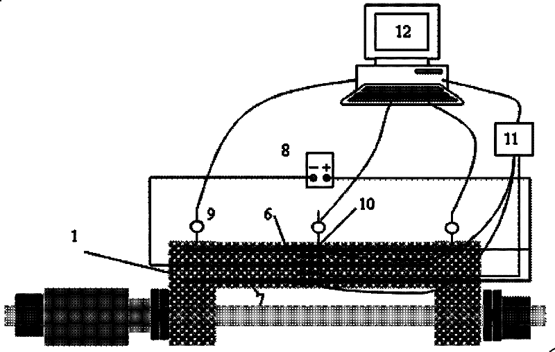
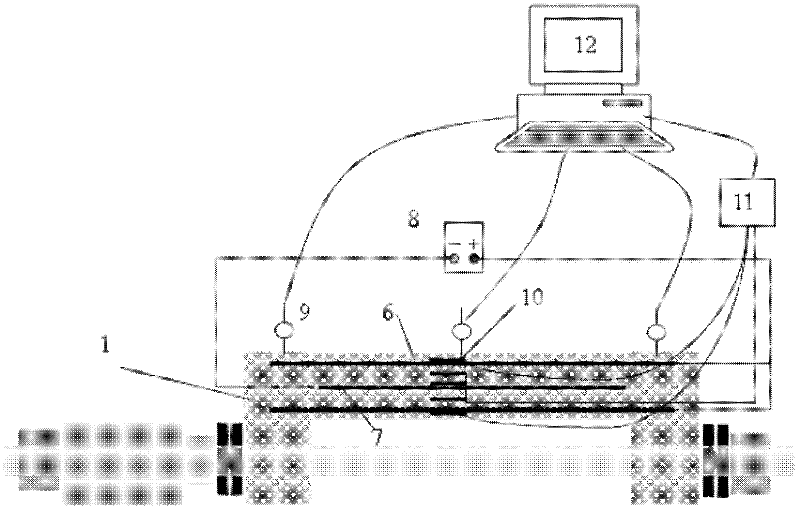
A test device and mechanical technology, which is applied in the field of civil engineering, can solve the problems of recording, unable to simulate the use load of structural components, and not considering the influence of environmental effects on the mechanical properties of components, etc.

Inactive Publication Date: 2012-03-28
ZHEJIANG COLLEGE OF CONSTR
View PDF4 Cites 28 Cited by
  • Summary
  • Abstract
  • Description
  • Claims
  • Application Information

AI Technical Summary

Problems solved by technology

However, there is no experimental device for the mechanical performance of reinforced concrete columns under the coupling of load and environment
[0003] The existing reinforced concrete columns are all tested on the long column test machine or the steel structure reaction frame test bench. This kind of test is generally a destructive test, without considering the influence of the environment on the mechanical properties of the component, and without considering the continuous The influence of load, let alone test the decay and degradation performance of components under the coupling action of load and environment
[0004] The existing rapid corrosion method is generally carried out in sodium chloride solution. Since the measuring instruments and instruments cannot work underwater, it is impossible to perform real-time measurement and analysis of mechanical performance indicators such as load-deflection, load-strain and crack development of components. Record
Although the artificial environment simulation box can simulate the real environment, it still cannot simulate the use load of the structural components in the working state. In addition, the instruments and meters arranged in the artificial environment simulation box will also be corroded, which makes the measurement impossible

Method used


Image

  • Test device for time varying mechanical properties of column under load-environment coupling effect
  • Test device for time varying mechanical properties of column under load-environment coupling effect
  • Test device for time varying mechanical properties of column under load-environment coupling effect

Examples


Embodiment 1

[0034] (a) Fabrication of reinforced concrete columns. The section size of the column is 120×120mm, the height is 750mm, the main reinforcement of the column is 4φ10, the stirrup is φ650-100, the protective layer is 15mm, and a plastic sheath with a length of 600mm and a diameter of 1.5mm is connected to the end of each main reinforcement Copper wire, the wire is first wound twice on the main reinforcement and tightened, then soldered with solder, and finally wrapped with epoxy resin, and the main reinforcement strain gauge is pasted in the longitudinal middle of the main reinforcement. Plastic sheathed copper wire. Bind the main reinforcement cage with steel binding wires, and then pour concrete to form it. When pouring, a φ6 stainless steel electrode 7 with a length of 450mm is embedded inside the column. The electrode 7 is connected to the outside of the concrete by wires. After 2 days of molding, the mold is removed and cured in a standard curing room for 28 days.

[003...


PUM


Abstract

Relating to the field of civil engineering, the invention provides a test device for time varying mechanical properties of a column under a load-environment coupling effect. The device comprises a column, a loading system, an environment corrosion accelerating system, and a measuring system. Specifically, the column is installed on the loading system which imposes a load on the column; the column is also in connection with the environment corrosion accelerating system so as to accelerate environment corrosion of the column; and the column is connected to the measuring system for real-time monitoring of time varying mechanical properties of the column. In the corrosion acceleration process of a member, the device of the invention not only can realize real-time observation of a member deflection change and the stress strain changes of steel bars and concrete, but also can observe the whole cracking and development process of a crack on the column during degradation, thus simulating the actual working state of the column completely, and successfully providing a solution to monitoring of time varying degraded mechanical properties of a reinforced concrete column under a load-environment coupling effect.

Description

technical field [0001] The invention relates to the field of civil engineering, and more specifically relates to a test device for the mechanical properties of a column under the coupled action of load and environment, and is especially suitable for the occasion of studying the time-varying mechanical properties of reinforced concrete columns under the coupled action of environment and load. Background technique [0002] Concrete structures work under a certain load, and are subjected to the synergistic effects of various factors such as hardening, penetration, freeze-thaw, and chemical erosion. A large number of concrete durability results under no load cannot reasonably reflect the actual state of the structure. . For this reason, the study of the long-term time-varying mechanical properties of reinforced concrete members under the coupling of load and environment has become a hot and difficult point in the field of civil engineering research. However, there is no experim...

Claims


Application Information

Patent Timeline
IPC IPC(8): G01N3/00G01N17/00
Inventor 李强胡颖崔巍陈益滨
Owner ZHEJIANG COLLEGE OF CONSTR
Learn More