
FPGA (field programmable gate array) based system and method for measuring speed of fan

A fan and speed measurement technology, applied in pump testing, liquid variable capacity machinery, machines/engines, etc., can solve problems such as many equipment and poor speed measurement accuracy

Active Publication Date: 2012-03-28
DAWNING INFORMATION IND BEIJING +1
View PDF3 Cites 6 Cited by
  • Summary
  • Abstract
  • Description
  • Claims
  • Application Information

AI Technical Summary

Problems solved by technology

[0005] Patent application number CN200610123553.1, the patent titled detection device and method for detecting fan speed, proposes a method of using photoelectric sensing equipment to test the speed according to the difference in the strength of the optical signal corresponding to the different fan speeds. This patent is also It is mainly used for production testing, and the device uses more equipment, and the speed measurement accuracy is poor

Method used


Image

  • FPGA (field programmable gate array) based system and method for measuring speed of fan
  • FPGA (field programmable gate array) based system and method for measuring speed of fan

Examples


Embodiment Construction

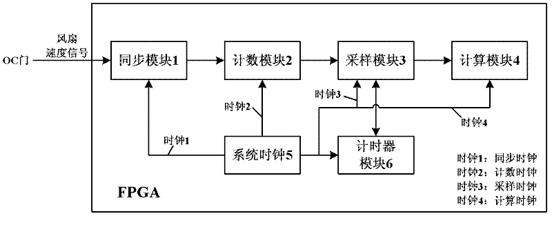
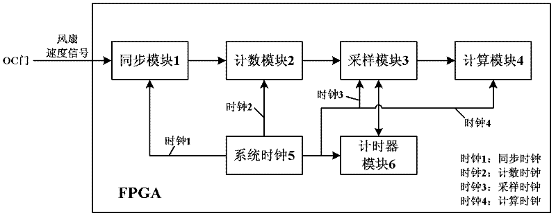
[0053] Structural schematic diagram of the present invention is attached figure 1 As shown, the FPGA is mainly composed of functional modules such as synchronization module 1, counting module 2, sampling module 3, calculation module 4, system clock 5, and timer module 6. All modules are provided with a 250MHz clock by the system clock module 5. The functions of each module are as follows:

[0054] (1) The fan speed signal input to the FPGA through the OC gate is a 3.3V level signal with a certain frequency. The frequency of this signal is related to the speed of the fan. It is generally several hundred Hz in stable operation, and the frequency in the startup phase is lower;

[0055] (2) In order to accurately capture the edge of the speed signal, the synchronization module 1 uses a 250MHz synchronous clock to accurately identify the rising edge of the fan speed signal and synchronize it to the 250MHz clock domain;

[0056] (3) The synchronized single pulse signal is used as t...


PUM


Abstract

The invention provides an FPGA (field programmable gate array) based method for measuring the speed of a fan. The FPGA is internally provided with the following functional modules: a synchronization module (1), a counting module (2), a sampling module (3), a calculating module (4), a system clock module (5) and a timer module (6), wherein 250MHz clock is supplied to all the modules by the system clock module (5). Compared with the prior art, the FPGA based method for measuring the speed of the fan has the beneficial effects: according to the technical scheme, basically no additional device is added to an FPGA board card with the fan and only a signal of the fan needs to be input through an OC (open collector) gate; according to the scheme, few resources are occupied in the FPGA, thereby achieving a very practical added value function of a board card system; and an accurate result of the rotating speed of the fan can be considered as a reference for judging if a working temperature of the board card is abnormal.

Description

technical field [0001] The invention belongs to the technical direction of fan speed measurement in the field of system signal detection, and provides a system and method for using FPGA to measure fan speed. Background technique [0002] On PC systems or board systems, fans have become an essential cooling device. Existing patents on fan speed detection generally focus on detecting the quality of fans during the trial production stage. This patent is only aimed at the speed detection of fans with good quality after normal power-on in the workplace, and is used for system monitoring. Most of the commonly used fans are PWM fans, where PWM stands for Pulse Width Modulation (Pulse Width Modulation), fan speed is usually measured according to the percentage of pulse width (duty cycle), and some other PWM fans also have some Ways, such as using a signal generator to generate a PWM wave with a certain frequency and duty cycle required, and then using a tachometer to compare and me...

Claims


Application Information

Patent Timeline
IPC IPC(8): F04B51/00
Inventor 张英文李静窦晓光刘朝辉邵宗有
Owner DAWNING INFORMATION IND BEIJING
Learn More