Elevator self-help system
An elevator system and elevator technology, applied in elevators, transportation and packaging, etc., can solve the problems that users cannot effectively save themselves
- Summary
- Abstract
- Description
- Claims
- Application Information
AI Technical Summary
Problems solved by technology
Method used
Image
Examples
no. 1 example
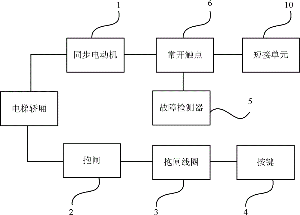
[0024] Such as figure 1 As shown, the elevator self-rescue system of this embodiment includes a synchronous motor 1 , a brake 2 , a brake coil 3 , a button 4 , a fault detector 5 , a normally open contact 6 and a shorting unit 10 .
[0025] Wherein the synchronous motor 1 is electrically connected to the short-circuit unit 10 through the normally open contact 6, the short-circuit unit 10 is used to short-circuit the motor, and the brake coil 3 is connected to the brake 2 is connected and when the brake coil 3 is turned on, the brake 2 is opened, and the elevator car starts to move, otherwise the brake 2 brakes the elevator car, and the elevator is in a static state. In this embodiment, the release action of the brake 2 is realized by controlling the brake coil in the brake 2 .
[0026] The brake coil 3 is also connected to the button 4. When the user presses the button 4, the button 4 is connected to the brake coil 3, and the formed loop makes the brake coil 3 also conduct. ...
no. 2 example
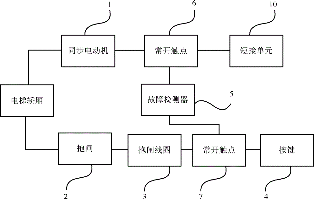
[0038] Such as figure 2 As shown, the difference between this embodiment and the first embodiment is that the elevator self-rescue system in this embodiment also includes a normally open contact 7, and the normally open contact 7 is connected in series with the brake coil 3 and the button between 4.
[0039] Wherein when the elevator fails, the fault detector 5 also closes the normally open contact 7 , so that a path is formed between the brake coil 3 and the button 4 . At this time, the user can make the conduction between the button 4 and the brake coil 3 to release the brake 2, so that the elevator car enters the leveling area, so it is convenient for the user to save himself.
[0040] In this embodiment, the brake coil 3 and the button 4 are isolated by the normally open contact 7, so as to prevent the user from misoperation when the elevator is in normal operation, that is, when the elevator is in normal operation, the user cannot control it through the button 4 The br...
no. 3 example
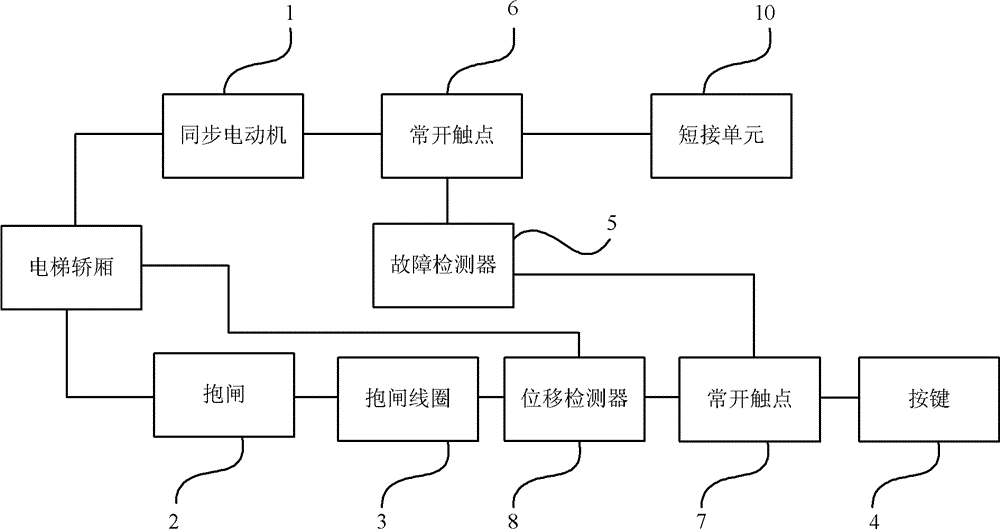
[0042] Such as image 3 As shown, the difference between this embodiment and the second embodiment is that the elevator self-rescue system in this embodiment also includes a displacement detector 8, and the displacement detector is used to detect whether the car of the elevator reaches the bottom of the elevator shaft or top.
[0043] In this embodiment, the displacement detector 8 is arranged between the normally open contact 7 and the brake coil 3. In addition, the user can also connect the displacement detector 8 with other components according to the design and structure of the elevator system. For example, the displacement detector 8 is arranged between the normally open contact 7 and the key 4 and the like.
[0044] Wherein when the elevator fails, when the displacement detector 8 does not detect that the car of the elevator reaches the bottom or the top of the elevator shaft, the conduction between the brake coil 3 and the displacement detector 8, so the brake coil 3 ...
PUM
 Abstract
Description
Claims
Application Information
 - R&D
- Intellectual Property
- Life Sciences
- Materials
- Tech Scout
- Unparalleled Data Quality
- Higher Quality Content
- 60% Fewer Hallucinations
Browse by: Latest US Patents, China's latest patents, Technical Efficacy Thesaurus, Application Domain, Technology Topic, Popular Technical Reports.
© 2025 PatSnap. All rights reserved.Legal|Privacy policy|Modern Slavery Act Transparency Statement|Sitemap|About US| Contact US: help@patsnap.com


