A New Gate Modulation Readout Circuit Structure
A readout circuit and gate modulation technology, applied in logic circuits, electrical components, pulse technology, etc., can solve the problems of inability to apply deep submicron integrated circuit technology, inability to effectively suppress short channel effects, and small MOS tubes. Achieve the effect of suppressing short channel effect, simple structure and eliminating DC current
- Summary
- Abstract
- Description
- Claims
- Application Information
AI Technical Summary
Problems solved by technology
Method used
Image
Examples
Embodiment Construction
[0022] Below the present invention will be further described in conjunction with the embodiment in the accompanying drawing:
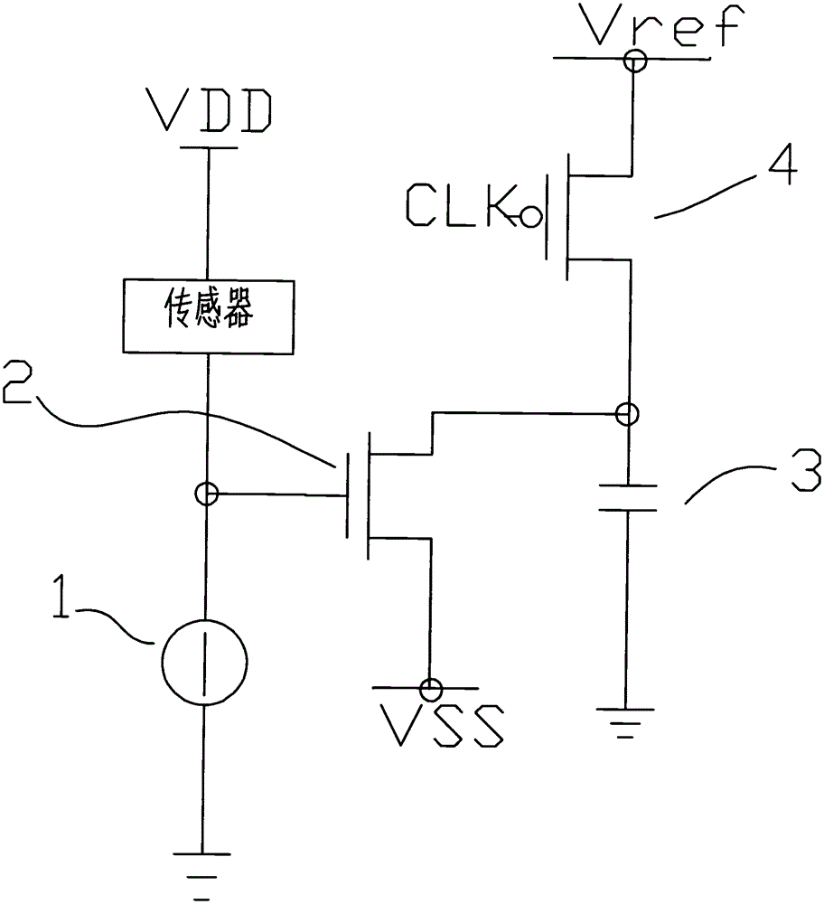
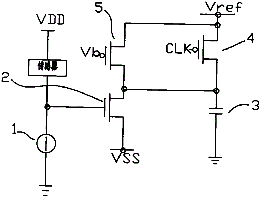
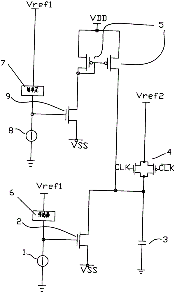
[0023] like image 3 As shown, the present invention is a novel grid modulation readout circuit structure, which is composed of a signal readout module, a DC offset elimination module, an integrating capacitor 3 and a reset switch 4 . The signal readout module is composed of a sensor 6 , a sensor DC bias circuit 1 and a first grid modulation NMOS transistor 2 . The DC bias elimination module is composed of a dark unit 7 , a dark unit DC bias circuit 8 , a second grid modulation NMOS tube and a current mirror 5 . The reset switch 4 is realized by a transmission gate composed of complementary NMOS and PMOS transistors.
[0024] The sensor DC bias circuit 1 of the signal readout module is connected to the output terminal of the sensor 6 to provide a DC current bias for the sensor so that the sensor can work normally. When the sensor is working normally...
PUM
 Abstract
Description
Claims
Application Information
 - R&D
- Intellectual Property
- Life Sciences
- Materials
- Tech Scout
- Unparalleled Data Quality
- Higher Quality Content
- 60% Fewer Hallucinations
Browse by: Latest US Patents, China's latest patents, Technical Efficacy Thesaurus, Application Domain, Technology Topic, Popular Technical Reports.
© 2025 PatSnap. All rights reserved.Legal|Privacy policy|Modern Slavery Act Transparency Statement|Sitemap|About US| Contact US: help@patsnap.com


