
Pressure sampling head of Pitotbar flow sensor

A technology of flow sensor and pressure-taking head, which is applied to the volume/mass flow generated by mechanical effects, and the direction of fluid flow detection by measuring differential pressure. It can solve the problem that the accuracy and precision are not very high and the pressure-taking effect is not very good problem, to achieve the effect of good pressure taking effect, high accuracy and precision

Active Publication Date: 2012-03-21
LIAONING BITOBAR TECH CO LTD
View PDF5 Cites 5 Cited by
  • Summary
  • Abstract
  • Description
  • Claims
  • Application Information

AI Technical Summary

Problems solved by technology

[0007] The pressure-taking body of the pressure-taking head of this Bitoba flow sensor is a uniform cylindrical shape, and the total pressure hole and the static pressure hole are on the side wall of the cylindrical pressure-taking head body. When used, the pressure-taking effect is not very good. , the accuracy and precision are not very high

Method used


Image

  • Pressure sampling head of Pitotbar flow sensor
  • Pressure sampling head of Pitotbar flow sensor
  • Pressure sampling head of Pitotbar flow sensor

Examples


Embodiment Construction

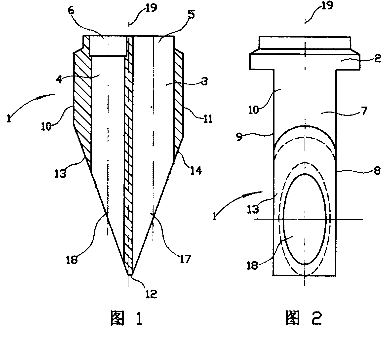
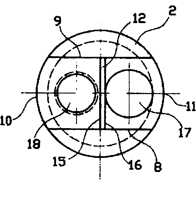
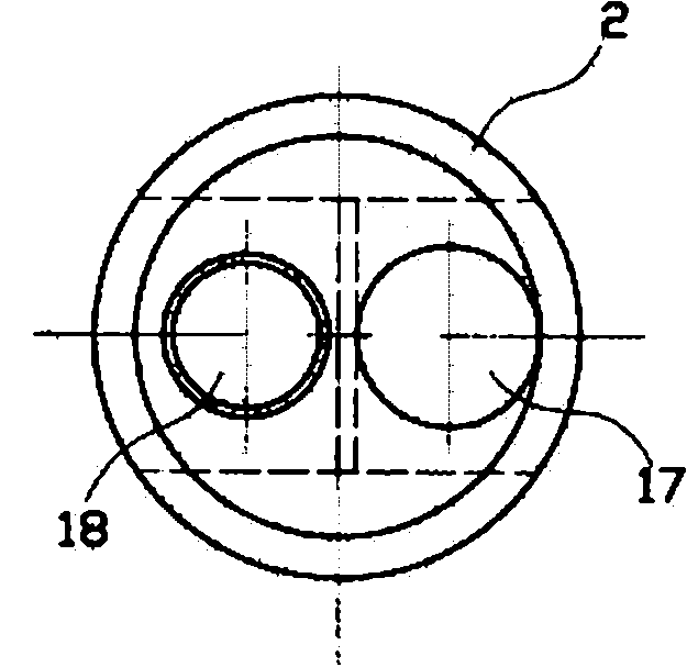
[0019] Figure 1~Figure 3 Among them, the pressure head of the Bitoba flow sensor has a pressure head body 1, and the upper end of the pressure head body has a cylindrical upper joint 2 perpendicular to the axis 19 of the pressure head body. The axis of the body is parallel to the total pressure channel 3 and the static pressure channel 4. The total pressure channel and the static pressure channel have the total pressure channel port 5 and the static pressure channel port 6 at the upper end of the pressure head body. The lower section of the pressure head body is the axis and the static pressure channel. Take the drum-shaped column 7 whose axis of the pressure head body is on the same straight line. The lower end surface 12 of the shaped column is perpendicular to the axis of the pressure head body, and there are left and right inclined surfaces 13, 14 respectively between the two arc surfaces and the lower end surface of the drum-shaped column. The angles of the included ang...


PUM


Abstract

The invention provides a pressure sampling head of a Pitotbar flow sensor. A cylindrical upper joint perpendicular to the axis of the pressure sampling head is arranged at the upper end of the pressure sampling head; a total pressure channel and a static pressure channel are arranged in the pressure sampling head; a total pressure channel opening and a static pressure channel opening are arrangedat the upper end of the pressure sampling head; a drum-shaped column is arranged on the lower section of the pressure sampling head; inclined surfaces are respectively arranged between two arc-shapedsurfaces of the drum-shaped column and the lower end surface of the drum-shaped column; a total pressure hole connected with the total pressure channel is formed on one inclined surface, and a staticpressure hole connected with the static pressure channel is arranged on the other inclined surface; and the axes of the total pressure hole and the static pressure hole are positioned on the same straight line and perpendicular to a pressure sampling head body. The drum-shaped column is arranged on the lower section of the pressure sampling head, the inclined surfaces are respectively arranged between the two arc-shaped surfaces of the drum-shaped column and the lower end surface of the drum-shaped column, the total pressure hole connected with the total pressure channel is formed on one inclined surface, the static pressure hole connected with the static pressure channel is arranged on the other inclined surface, and the axes of the total pressure hole and the static pressure hole are positioned on the same straight line and vertical to a pressure sampling head body. When the pressure sampling head is in use, the pressure sampling effect is good, and the accuracy degree and the precision degree are high.

Description

technical field [0001] The invention relates to a pressure-taking head of a bitobar flow sensor, in particular to a lower end orifice of the pressure-taking head of a bitobar flow sensor. Background technique [0002] Pitobar flow sensor is designed according to the Pitot tube principle invented by French scientist H.Pitot. Pitot tube is also called Pitot tube. Bar is a pressure unit. [0003] The Bitoba flow sensor has a straight pipe-shaped pressure guiding tube. The pressure guiding tube has an outer tube and an inner tube inside the outer tube. The upper ends of the outer tube and the inner tube of the pressure guiding tube are the total pressure interface and the static pressure interface respectively. The lower end of the shaped pressure guiding tube has a pressure taking head, the pressure taking head has a cylindrical pressure taking head body, the upper end of the pressure taking head body has an upper joint that can be connected with the lower end of the pressure g...

Claims


Application Information

Patent Timeline
IPC IPC(8): G01F1/46
Inventor 王忠辉
Owner LIAONING BITOBAR TECH CO LTD
Learn More