Phase-locked circuit and radio communicating device

A phase-locked circuit and phase-locked technology, applied in the adjustment of resonant circuits, electrical components, automatic power control, etc., to achieve the effect of alleviating phase noise design and eliminating frequency correction errors

Inactive Publication Date: 2012-03-14
SONY CORP
View PDF1 Cites 17 Cited by
  • Summary
  • Abstract
  • Description
  • Claims
  • Application Information

AI Technical Summary

Problems solved by technology

[0059] It is very important that the wrong frequency band is not selected in this frequency calibration

Method used


Image

  • Phase-locked circuit and radio communicating device
  • Phase-locked circuit and radio communicating device
  • Phase-locked circuit and radio communicating device

Examples


Embodiment Construction

[0094] Preferred embodiments of the present disclosure will be described below with reference to the accompanying drawings.

[0095] Incidentally, description will be made in the following order.

[0096] 1. Basic configuration of RF transceiver (radio communication equipment) and PLL

[0097] 2. Frequency Calibration Circuit Configuration and Calibration Sequence

[0098]

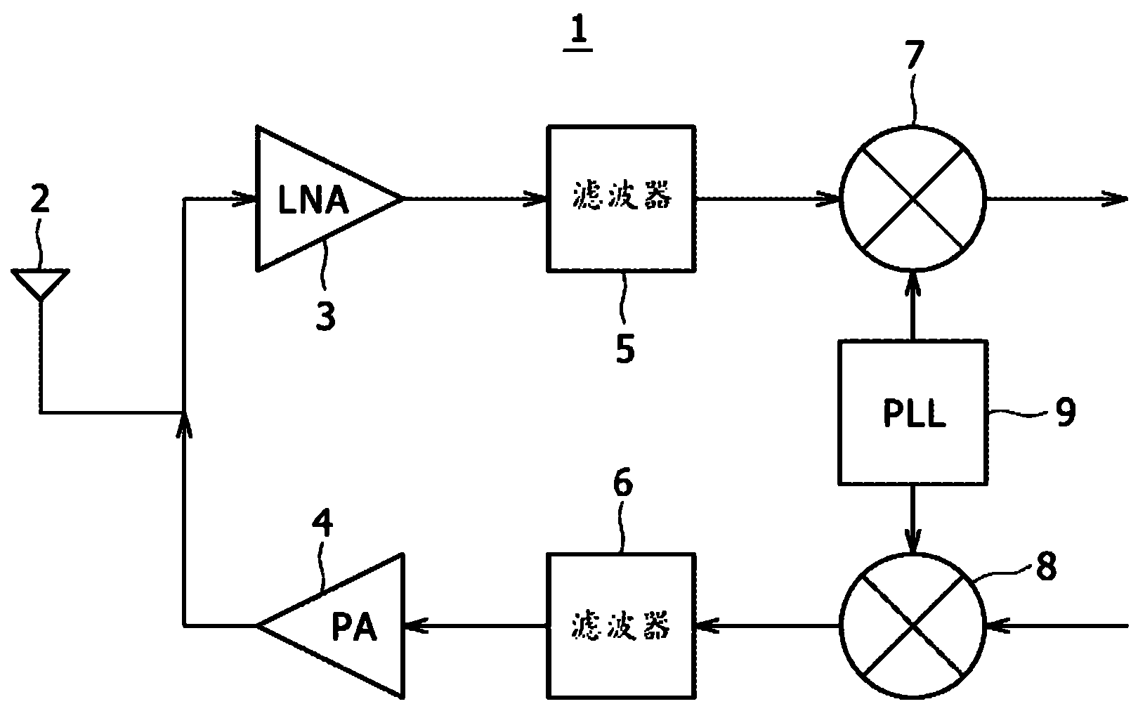
[0099] Figure 9 is a diagram showing an example of a configuration of an RF transceiver as a radio communication device according to an embodiment of the present disclosure.

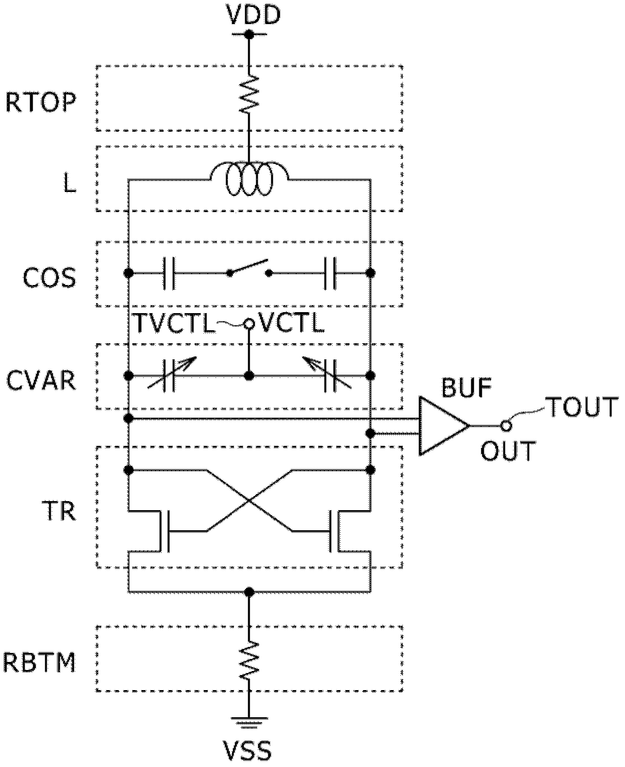
[0100] Figure 10 is a diagram showing an example of a configuration of a PLL (frequency synthesizer) including a calibration circuit according to an embodiment of the present disclosure.

[0101] Figure 9The RF transceiver 100 has an antenna 110 , an LNA (Low Noise Amplifier) ​​120 , a PA (Power Amplifier) ​​130 , and filters 140 and 150 .

[0102] The RF transceiver 100 has a mixer 160 as a first frequency conversion sect...


PUM


Abstract

Disclosed herein is a phase-locked circuit including: a phase-locked section including a voltage controlled oscillator having a capacitance bank and changing oscillation frequency according to voltage information, the phase-locked section phase-locking an oscillating signal of the voltage controlled oscillator to a reference signal; and a calibration section having a voltage correcting function for supplying an appropriate calibration voltage to the voltage controlled oscillator in performing frequency calibration for the voltage controlled oscillator; the calibration section including a counter circuit, a first storage circuit and a second storage circuit, a comparator circuit, a control circuit, a voltage generating circuit, and a processing circuit.

Description

technical field [0001] The present disclosure relates to a phase-locked circuit and a radio communication device, which include a calibration circuit with a voltage correction function for supplying a voltage-controlled oscillator with an appropriate calibration voltage. Background technique [0002] Now, in RF transceivers, frequency synthesizers may be essential as local oscillators that can achieve high-precision output frequencies. [0003] figure 1 is a diagram showing a typical configuration of an RF transceiver. [0004] figure 2 is showing figure 1 A diagram of a typical configuration of a PLL (frequency synthesizer) in . [0005] figure 1 The RF transceiver 1 has an antenna 2, a low noise amplifier (LNA) 3, a power amplifier (PA) 4, filters 5 and 6, mixers 7 and 8, and a phase lock circuit (PLL: lock phase ring) 9. [0006] figure 2 The PLL 9 has a phase comparator (phase frequency detector: PFD) 10 , a charge pump (CP) 11 , and a loop filter (LF) 12 . ...

Claims


Application Information

Patent Timeline
Patent Type & Authority Applications(China)
IPC IPC(8): H03L7/099H03L7/18H04B1/40H03L7/087H03L7/187
CPCH03J2200/10H03L7/102H03L2207/06
Inventor 藤原彻哉原田真吾
Owner SONY CORP
Why Eureka
Try Eureka