
Band gap reference circuit and band gap reference current source

A reference current source and reference circuit technology, applied in the direction of adjusting electrical variables, control/regulation systems, instruments, etc., can solve the problems of increasing power consumption of bipolar transistors Q1 and Q2, unable to reduce input voltage, and layout area consumption

Active Publication Date: 2012-03-14
NOVATEK MICROELECTRONICS CORP
View PDF5 Cites 14 Cited by
  • Summary
  • Abstract
  • Description
  • Claims
  • Application Information

AI Technical Summary

Problems solved by technology

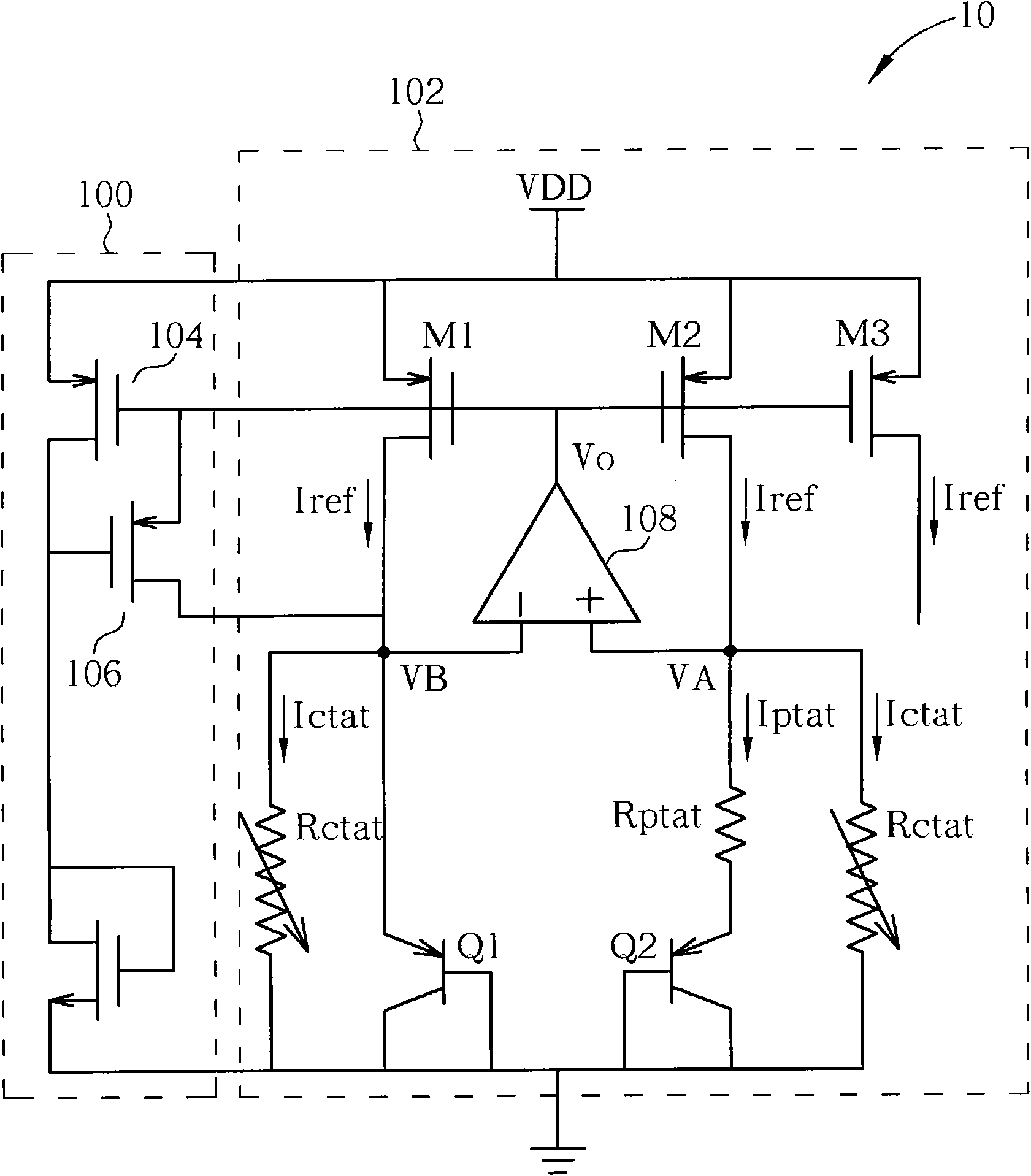
[0014] However, if figure 1 and Figure 2A As shown, when using a P-type MOS transistor input pair, the output voltage Vo is equal to the system voltage VDD minus the source-gate voltage difference VSGM1 of the current mirror M1, so when the system voltage VDD rises, it will cause the P-type MOS transistor input For entering the linear region (linear-region), the power amplifier 108 fails, and cannot adapt to the system voltage VDD with a wide operating range
In contrast, although the input pair of NMOS transistors can adapt to the system voltage VDD with a wide operating range, it cannot reduce the input voltage VA, VB, which increases the power consumption of the bipolar transistors Q1 and Q2
[0015] In addition, in the bandgap reference current source 10, the start-up condition of the start-up circuit 100 needs to be VDD>2VGS, which is prone to poor start-up under process variations and temperature changes, and the bandgap reference circuit 102 also needs to use a resistance value of L* The resistance of R to balance the negative temperature coefficient current, resulting in a large layout area consumption

Method used


Image

  • Band gap reference circuit and band gap reference current source
  • Band gap reference circuit and band gap reference current source
  • Band gap reference circuit and band gap reference current source

Examples


Embodiment Construction

[0042] Please refer to image 3 , image 3It is a schematic diagram of a bandgap reference current source 30 in an embodiment of the present invention. The bandgap reference current source 30 includes a startup circuit 300 and a bandgap reference circuit 302 . Compared with the start-up circuit 100, the start-up circuit 300 can start the operation of the energy bandgap reference circuit 302 when the system voltage VDD>VSG, and the start-up circuit 300 further includes a P-type metal oxide semiconductor transistor 304, which can be used in the energy bandgap After the reference circuit 302 stably outputs a zero temperature coefficient current Iref′, it is gradually turned off to avoid DC power consumption. In the bandgap reference circuit 302, the method for generating a positive temperature coefficient (proportional to absolute temperature, PTAT) current Iptat' and a negative temperature coefficient (complementary to absolute temperature, CTAT) current Ictat' is the same as ...


PUM


Abstract

The invention discloses a band gap reference circuit, which comprises a first double-carrier transistor, a first resistor, a second double-carrier transistor, a second resistor, a first operational amplifier, a second operational amplifier and a zero temperature coefficient current generator, wherein the first resistor is used for generating positive temperature coefficient current; the second resistor is used for generating negative temperature coefficient current; the first operational amplifier is coupled to the first double-carrier transistor and the first resistor; the second operational amplifier is coupled to the first double-carrier transistor and the second resistor; and the zero temperature coefficient current generator is used for totaling the positive temperature coefficient current and the negative temperature coefficient current so as to generate zero temperature coefficient current.

Description

technical field [0001] The invention relates to a bandgap reference circuit and a bandgap reference current source, in particular to a bandgap reference circuit and a bandgap reference current source with a smaller layout area. Background technique [0002] In analog circuit applications, a stable reference voltage source or current source that is not affected by temperature changes is often used to provide a reference voltage or reference current to monitor the correctness of the operation of the power supply or other circuits, and the bandgap reference circuit (Bandgap Reference Circuit) is such a circuit. In simple terms, the bandgap reference current source mixes and adds a current with a positive temperature coefficient (proportional to absolute temperature, PTAT) and a current with a negative temperature coefficient (complementary to absolute temperature, CTAT) in an appropriate ratio. After the temperature coefficient and the negative temperature coefficient cancel e...

Claims


Application Information

Patent Timeline
IPC IPC(8): G05F3/16
Inventor 胡敏弘丁振国吴振聪
Owner NOVATEK MICROELECTRONICS CORP
Learn More