
Center rocket type bimodal ramjet with circular structure

A ramjet and rocket-type technology, which is applied in the direction of rocket engine devices, ramjet engines, machines/engines, etc., can solve the problems of restricting the application of large-scale engines, small flame stability area, unfavorable processing and manufacturing, etc., to solve the problem of fuel Penetration and blending problems, safe and reliable operation, and simple structure

Inactive Publication Date: 2012-03-14
NORTHWESTERN POLYTECHNICAL UNIV
View PDF3 Cites 30 Cited by
  • Summary
  • Abstract
  • Description
  • Claims
  • Application Information

AI Technical Summary

Problems solved by technology

However, the length and depth ratio of the concave cavity and the fuel equivalent ratio all have a great influence on the flame stability performance, and the flame stability range of a single concave cavity is limited, and it is difficult to maintain good flame stability performance in the entire combustion chamber flow channel
Through research, it is found that the current dual-mode ramjet research process has the following shortcomings: First, the ignition and stable operating ranges are relatively narrow. 7 range; second, the range of the flame stabilization area is small, and the range of flame stabilization such as the concave cavity flame stabilizer and the wall induced flame is limited to the near wall area of ​​the combustion chamber, and can only be applied to small flames with an equivalent diameter of less than 200mm. The size of the engine limits the application of large-size engines in the engineering field; third, the dual structure combustion chamber is not conducive to the integration with the current advanced streamline tracing inlet and aircraft, and it is easy to form stress concentration, which is not conducive to processing and manufacturing

Method used


Image

  • Center rocket type bimodal ramjet with circular structure
  • Center rocket type bimodal ramjet with circular structure
  • Center rocket type bimodal ramjet with circular structure

Examples


Embodiment Construction

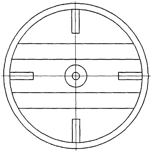
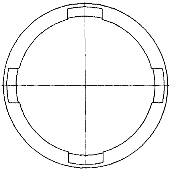
[0020] This embodiment is a center rocket dual-mode ramjet with a circular structure. The dual-mode ramjet includes an equipment nozzle 1, an isolation section 2, a main support plate 3, a central rocket 4, a small support plate 5, a first-stage combustion chamber 6, a cavity 7, a second-stage combustion chamber 8, and an expansion section 9.

[0021] figure 1 The structure of the dual-mode ramjet is shown. The isolation section 2, the first-stage combustion chamber 6, the second-stage combustion chamber 8, and the expansion section 9 are threaded through, and the cross-sections are circular structures; the equipment nozzle 1 is installed in the isolation Before segment 2, it is used to simulate the compression effect of the intake port in a real engine. The main support plate 3 is arranged in the isolation section 2. In order to ensure the symmetry of the flow field, it penetrates up and down along the symmetry plane of the isolation section 2; the central rocket 4 is installed ...


PUM


Abstract

The invention discloses a center rocket type bimodal ramjet with a circular structure. in the bimodal ramjet, a circular-structured combustion chamber is adopted, a center rocket is installed in a separation section, and the high-temperature fuel-rich gas of the center rocket can be used as an effective ignition source and a flame stabilization source; a small support plate group is used to inject secondary fuel so as to perform secondary burning together with incoming flow air tissue. The injection of the secondary fuel is stepwise carried out along the axial direction of the engine, wherein the support plate directly performs injection in a primary combustion chamber, a concave cavity performs forward injection in a secondary combustion chamber, and the support plate performs injection in the secondary combustion chamber as well after the support plate is installed. The engine provided by the invention has simple structure, is easy to process, safe and reliable to operate, is more suitable for application of the bimodal ramjet with larges size structure in an actual project.

Description

Technical field [0001] The invention relates to an air-breathing hypersonic dual-mode ramjet structure, in particular to a circular structure dual-mode ramjet with a central support plate rocket. It belongs to the technical field of rocket engines and is suitable for dual-mode ramjet engines with large diameters and high performance. Background technique [0002] In the research process of dual-mode ramjet, how to achieve reliable ignition, efficient combustion and high integration of engine and aircraft in a larger-scale combustion chamber has become the most critical issue. At present, the commonly used dual-mode ramjet design method is that the combustion chamber adopts a binary structure with a rectangular cross section. The ignition methods include induced flame ignition, torch ignition, and igniter forced ignition ("Propulsion Technology", Vol.25, No. 6, 2004, 566-569). As mentioned in the article, the induction flame and torch ignition require additional fuel supply such...

Claims


Application Information

Patent Timeline
Patent Type & Authority Applications(China)
IPC IPC(8): F02K9/62F02K9/97F02K7/10
Inventor 吕翔李鹏飞汤祥秦飞魏祥庚刘洋刘佩进李江何国强
Owner NORTHWESTERN POLYTECHNICAL UNIV
Learn More