Brewery facility for producing and bottling beer

A technology for filling equipment and equipment, which is used in beer brewing, lighting and heating equipment, biochemical equipment and methods, etc., and can solve problems such as high energy density that cannot reach the maximum temperature level.

Inactive Publication Date: 2012-03-07
GEA BREWERY SYST
View PDF7 Cites 3 Cited by
  • Summary
  • Abstract
  • Description
  • Claims
  • Application Information

AI Technical Summary

Problems solved by technology

Therefore, the use of various energy generation methods for operating brewery plants is ruled out, since high energy densities with correspondingly high maximum temperature levels cannot be achieved in various energy generation methods, especially alternative energy generation methods

Method used


Image

  • Brewery facility for producing and bottling beer
  • Brewery facility for producing and bottling beer
  • Brewery facility for producing and bottling beer

Examples


Embodiment Construction

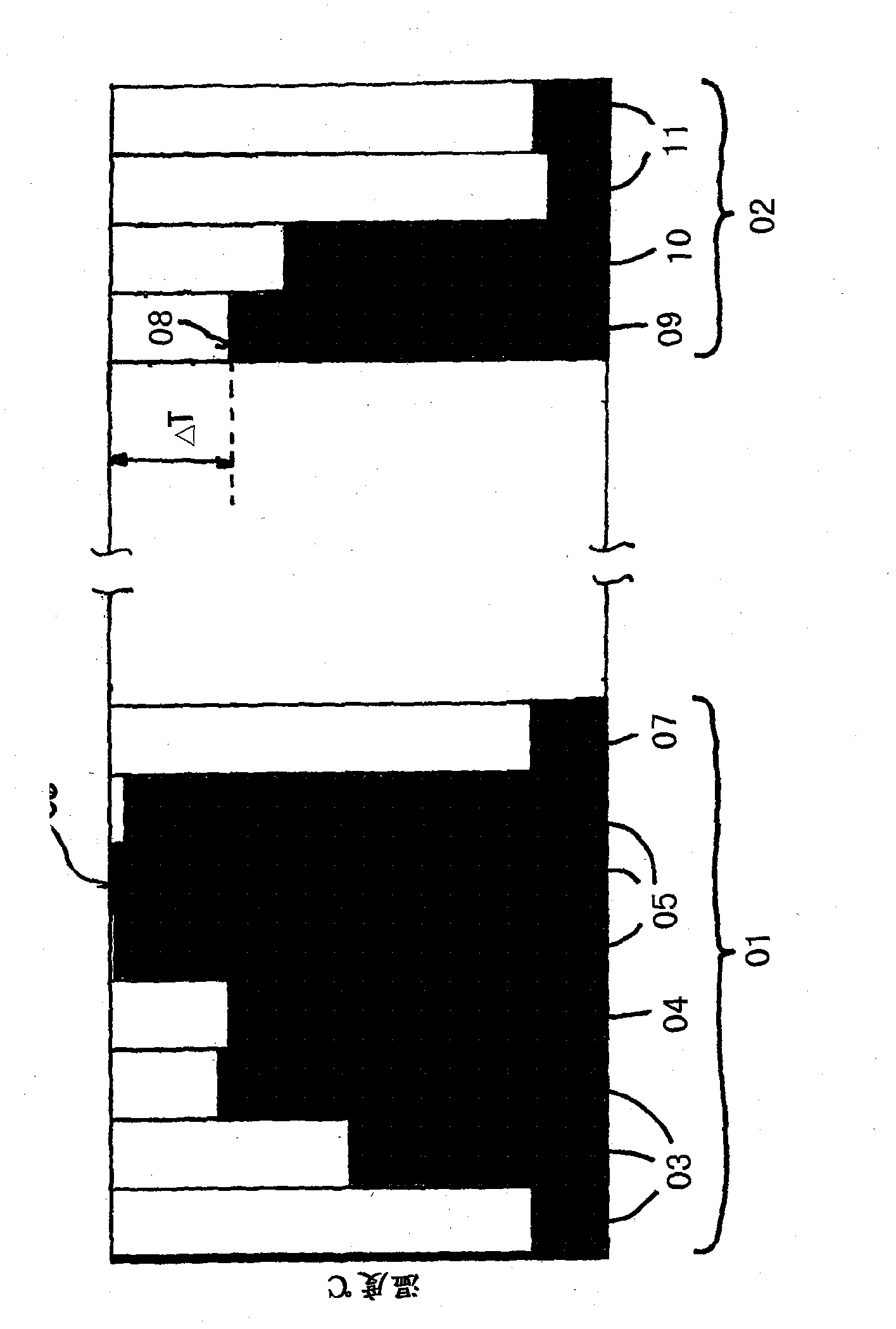
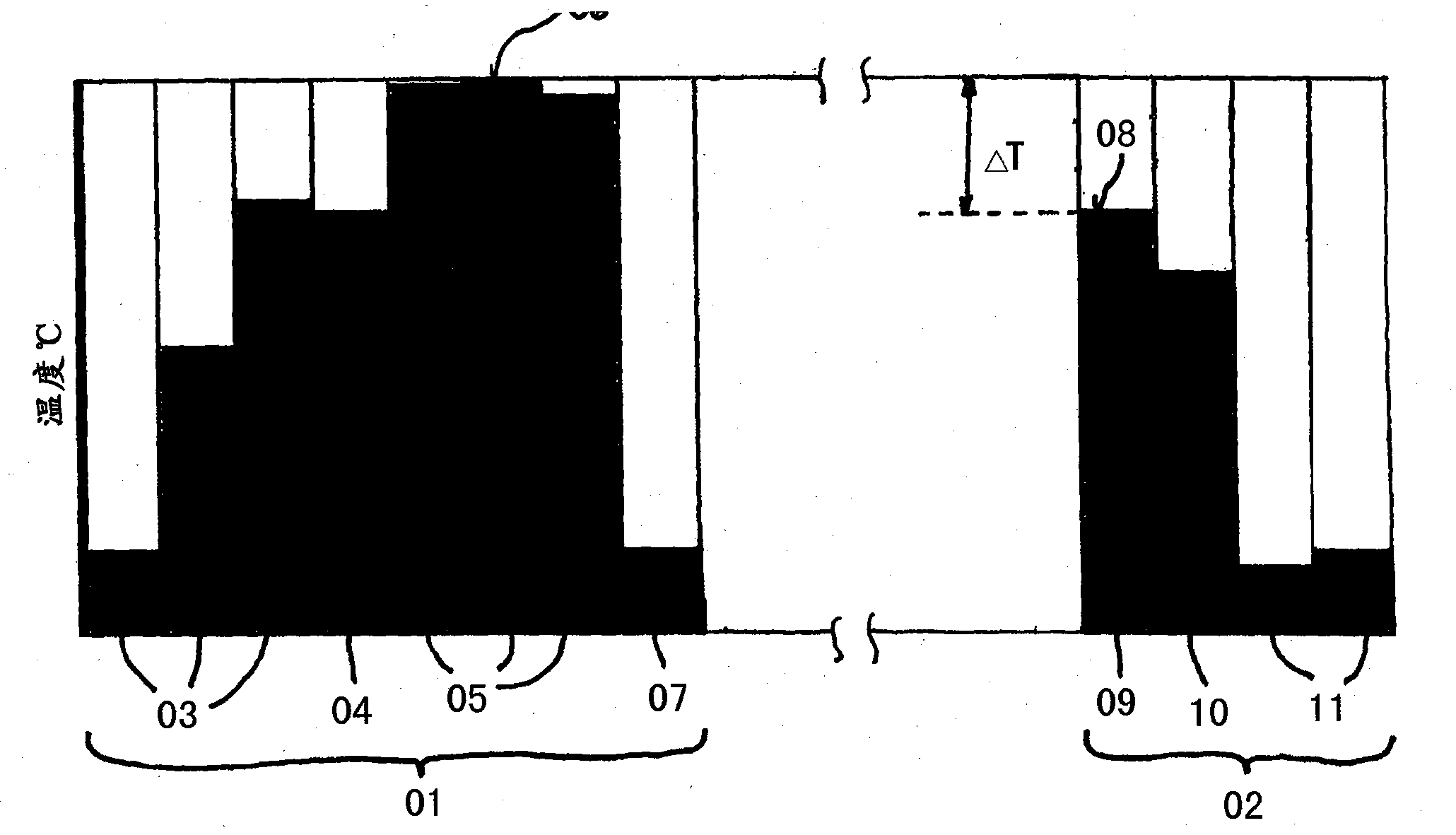
[0022] figure 1The temperature levels of a partial process are shown on the one hand in the brewhouse plant 01 and on the other hand in the filling plant 02 . Here, in the brewhouse plant 01 , the wort is successively heated up to a maximum temperature level 06 during a mashing process 03 , a refining process 04 and a wort boiling process 05 and subsequently cooled down in a wort cooling process 07 . The maximum temperature level 08 for the bottle washing process 09 is determined in the filling plant 02 , whereas the temperatures are significantly lower in the pasteurization process 10 and in the filling process 11 . The difference between the maximum temperature 06 in the brewing plant 01 and the maximum temperature 08 in the filling plant 02 is the basis of the brewing plant according to the invention, which has a function for supplying the brewing plant 01 with process heat and a separate energy supply grid supplying the filling plant 02 with process heat.

[0023] figu...


PUM


Abstract

The invention relates to a brewery facility (12) for producing and bottling beer, comprising a brewhouse facility (01) in which wort is produced from raw materials while employing process energy, and further comprising a bottling facility (02) in which the beer produced from the wort is bottled into packaging containers, in particular bottles, while employing process energy, wherein in order to supply the brewhouse facility (01) with process energy a first energy supply network (16) is provided, into which process energy having a first temperature level is fed from at least one first energy generation facility (17) and distributed by a heat exchanger to different energy consumers (14, 15) in the brewhouse facility (01), and wherein in order to supply the bottling facility (02) with process energy a second energy supply network (21) is provided,; into which process energy having a second temperature level is fed from at least one second energy generation facility (22) and distributed by a heat exchanger to different energy consumers (23, 24, 25) in the bottling facility (02), wherein the maximum temperature of the heat exchanger in the first energy supply network is above the maximum temperature of the heat exchanger in the second energy supply network.

Description

technical field [0001] The invention relates to a brewing plant for producing and filling beer according to the preamble of claim 1 . Background technique [0002] A brewing plant usually consists of several plant parts, so that beer wort is first produced step by step from raw materials in different plant parts, the beer wort is subsequently fermented into beer, and the drinkable beer is finally bottled middle. In this case, process energy is required in all plant parts in order to be able to carry out the different partial processes. Of the different plant parts of the brewing plant, only the brewhouse plant for producing beer malt and the filling plant for filling beer into bottles are of particular interest here for the invention described below. However, the brewing plant as a whole can of course also comprise other plant components. [0003] The invention relates to the most efficient energy supply of a brewery plant and in this case in particular to the particularl...

Claims


Application Information

Patent Timeline
Patent Type & Authority Applications(China)
IPC IPC(8): C12C13/00
CPCC02F11/04C02F2103/32C02F2303/10C12C13/00C12F3/06F24S21/00F24T10/00F28D15/00Y02E10/10Y02W10/20Y02W10/30Y02W10/37
Inventor 鲁道夫·米歇尔路德维格·舍勒格尔德·维甘德
Owner GEA BREWERY SYST
Why Eureka
Try Eureka