
Rotary compressor with air injection function

A technology of rotary compressor and air injection to increase enthalpy, applied in the field of compressors, can solve the problems of affecting the effect of increasing enthalpy, increasing the cost, and the effect of increasing enthalpy is not obvious, so as to improve the effect of increasing enthalpy, improve the energy efficiency of the system, and reduce the production cost Effect

Active Publication Date: 2015-09-09
GREE ELECTRIC APPLIANCES INC +1
View PDF4 Cites 0 Cited by
  • Summary
  • Abstract
  • Description
  • Claims
  • Application Information

AI Technical Summary

Problems solved by technology

[0004] (1) Regardless of whether it is a single-cylinder or double-cylinder roller compressor, the normal suction will be affected by the way of increasing enthalpy by air injection, resulting in no obvious effect of increasing enthalpy. The effect is very inconspicuous, and ultimately affects the use and promotion of enthalpy-enhancing compressors
[0005] (2) In the process of increasing enthalpy, as the pressure in the compression chamber increases, the enthalpy-increasing backflow will affect the effect of increasing enthalpy
In order to solve the enthalpy-increasing backflow, technicians designed a variety of injection devices, resulting in difficulty in assembling the enthalpy-increasing compressor and increasing the cost

Method used


Image

  • Rotary compressor with air injection function
  • Rotary compressor with air injection function
  • Rotary compressor with air injection function

Examples


Embodiment 1

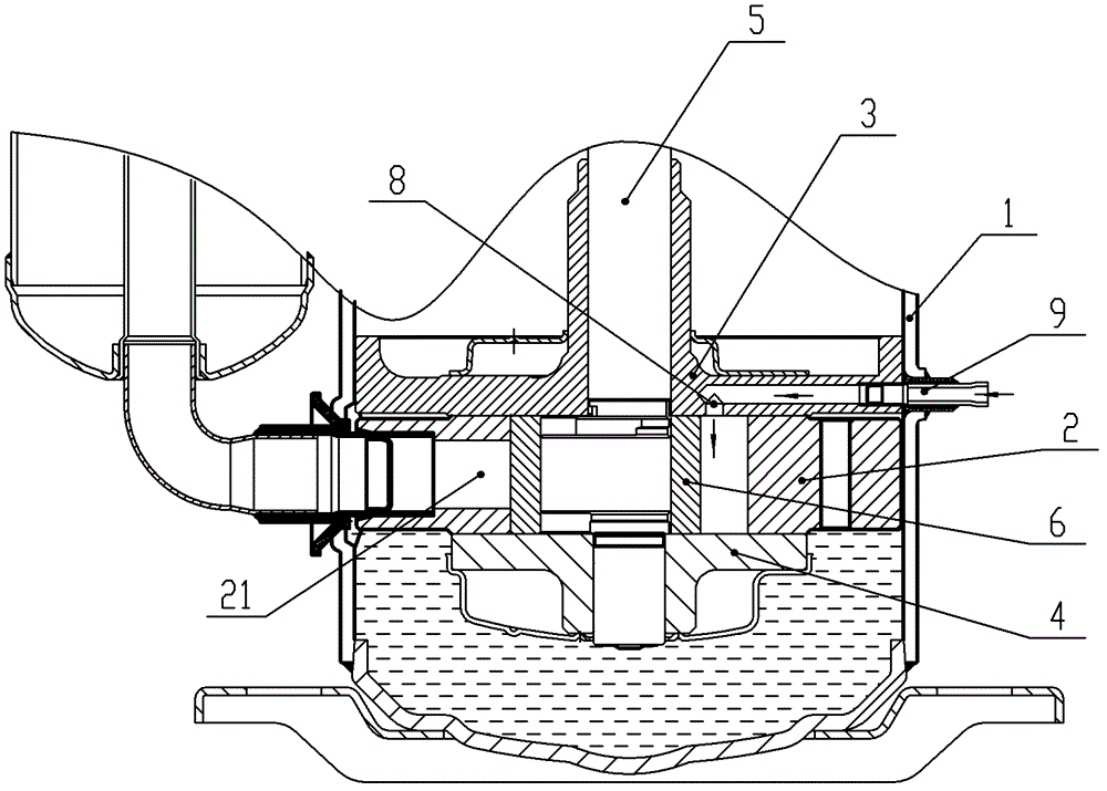
[0025] combine figure 1 and figure 2 As shown, the rotary compressor provided in this embodiment includes: a housing 1, a cylinder 2, an upper flange 3, a lower flange 4, a crankshaft 5, a roller 6, a sliding vane 7, a motor ( figure 1 not shown), etc. A radially telescopic sliding piece 7 is arranged in the cylinder 2, and the two sides of the sliding piece 7 are respectively provided with an air inlet 21 without an air suction valve and an air outlet with an air exhaust valve, and the upper flange 3 and the lower flange 4 are arranged on the The upper and lower ends of the cylinder 2 form a closed cylinder volume with the inner wall of the cylinder 2 . The roller 6 is installed on the eccentric crankshaft 5 , and the roller 6 rolls along the inner wall of the cylinder 2 to form a crescent-shaped working cavity 201 with the cylinder 2 . The sliding plate 7 relies on the force of the spring to make its end closely contact with the outer edge of the roller 6, and divides th...

Embodiment 2

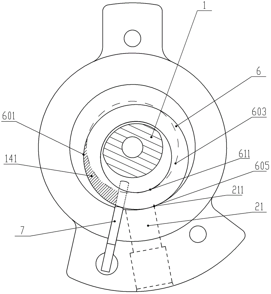
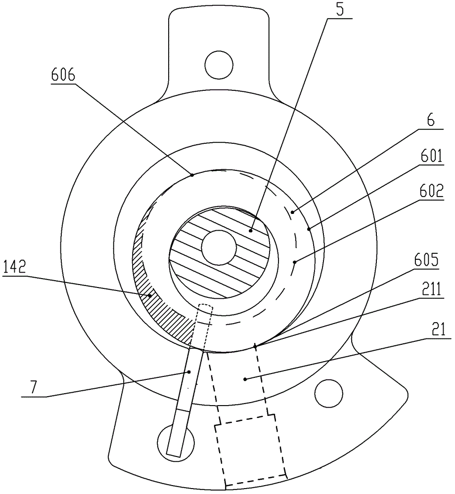
[0029] The difference between the second embodiment and the first embodiment is that the compressor in the first embodiment is a traditional cylinder wall suction hole, which has a suction clearance; the compressor used in the second embodiment adopts a lower flange (or In the case of upper flange and multi-stage cylinder, it may also be the way of the separator) suction hole, and there is no suction clearance volume in this way. For the compressor without clearance, the position of the air injection channel 8 at the end surface of the upper flange 3 has the following two situations:

[0030] (1) if Figure 4 shown, for R 1 +e>D 1 -R 2 compressor (where R 1 is the inner radius of the roller, e is the eccentricity, D 1 Roller outer diameter, R 2 inner radius of the cylinder), and the air injection port is set at: when the highest point 605 of the outer circle of the roller 6 (that is, the tangent point between the roller 6 and the inner wall of the cylinder) is located at...

Embodiment 3

[0033] Embodiment 1 and Embodiment 2 limit four different situations, the scope of the air injection channel 8 on the upper flange to open the air injection port, and the present embodiment 3 provides a specific setting scheme for the position of the air injection port and the process of increasing the enthalpy by air injection . Such as Figure 6 As shown, in order to better show the position of the opened air injection port relative to the slide plate 7 and the air intake port 21, the position of the air injection channel 8 is directly drawn with a dotted line on the upper end of the cylinder 2 in an intuitive manner in the figure, and The position where an air injection port 811 of the air injection channel 8 is located. In order to allow the air injection port 811 to open in time and increase the enthalpy increase, the air injection port 811 can be set in a half crescent shape, or a circular air injection port can be used.

[0034] combine Figure 6 to Figure 9 , the ai...


PUM


Abstract

The invention discloses a rotary compressor with the functions of injecting air and raising enthalpy. At least one air injection channel is arranged on an upper flange, a lower flange or a dual-cylinder separation board and is at least provided with at least one air injection port; the air injection port and the air injection channel are communicated with the inside of the air cylinder and the outside of the compressor; a roll end surface can be used for automatically controlling the opening and the closing of the air injection port in the rolling process of a roller; and the setting position of the air injection port meets the conditions that the air injection port is opened by the roller end surface at the initial stage of one compression stroke and is closed by the roller end surface at the late stage of the compression stroke. According to the rotary compressor disclosed by the invention, the technical difficult problem that air suction is influenced by the enthalpy rise of the rotary roller type compressor is solved; meanwhile, the enthalpy rise amount of the compressor is improved; the energy efficiency of the system is improved; and the aim of energy saving is achieved.

Description

technical field [0001] The invention relates to the technical field of compressors, in particular to a rotary compressor with the function of increasing enthalpy by gas injection. Background technique [0002] Air conditioning and heat pump systems generally include compressors, outdoor heat exchangers, primary and secondary throttling devices, flash evaporators, liquid storage tanks, indoor heat exchangers and pipelines connecting the above components, and their working principles will not be described here. When the air conditioning system is heating, as the outdoor temperature decreases, the suction temperature of the compressor also decreases. The traditional air-conditioning system uses a common compressor, which can achieve an ideal heating effect when the working condition is more than ten degrees, but when it is around minus twenty degrees, the heating capacity decays very seriously, and the heating capacity cannot reach the rated value , the heating effect is not i...

Claims


Application Information

Patent Timeline
Patent Type & Authority Patents(China)
IPC IPC(8): F04C18/356
Inventor 黎法运杜俊律陈迪松王方明王勇黄楷涛
Owner GREE ELECTRIC APPLIANCES INC
Learn More