Eureka AIR delivers breakthrough ideas for toughest innovation challenges, trusted by R&D personnel around the world.

Intelligent guarantee method for optical module in high temperature environment

A high-temperature environment, optical module technology, applied in the field of control, can solve the problems of module laser temperature rise, unfavorable laser drive circuit, unfavorable positive feedback loop, etc.

Inactive Publication Date: 2012-02-22
JIANGSU ALLRAY
View PDF0 Cites 10 Cited by
  • Summary
  • Abstract
  • Description
  • Claims
  • Application Information

AI Technical Summary

Problems solved by technology

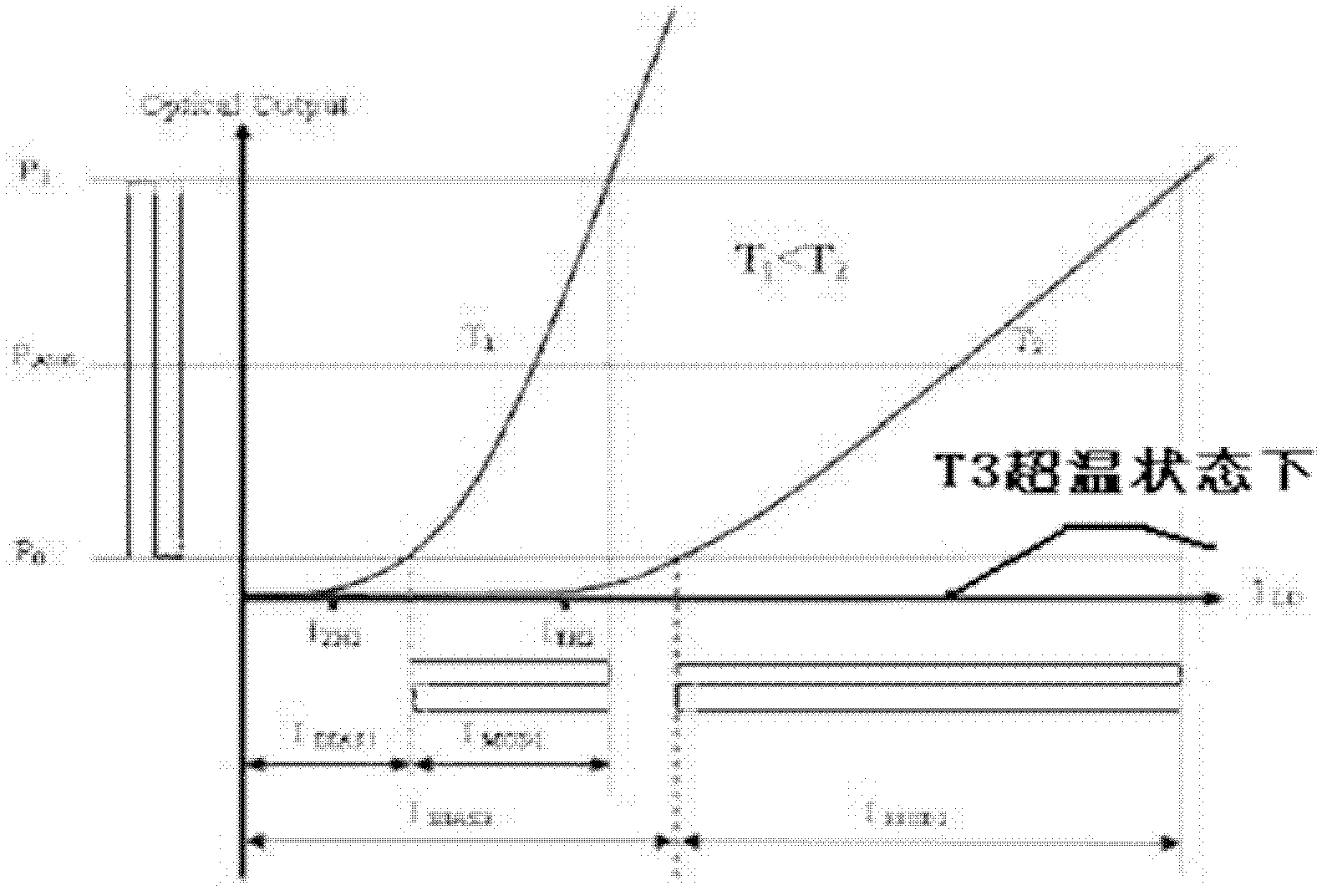
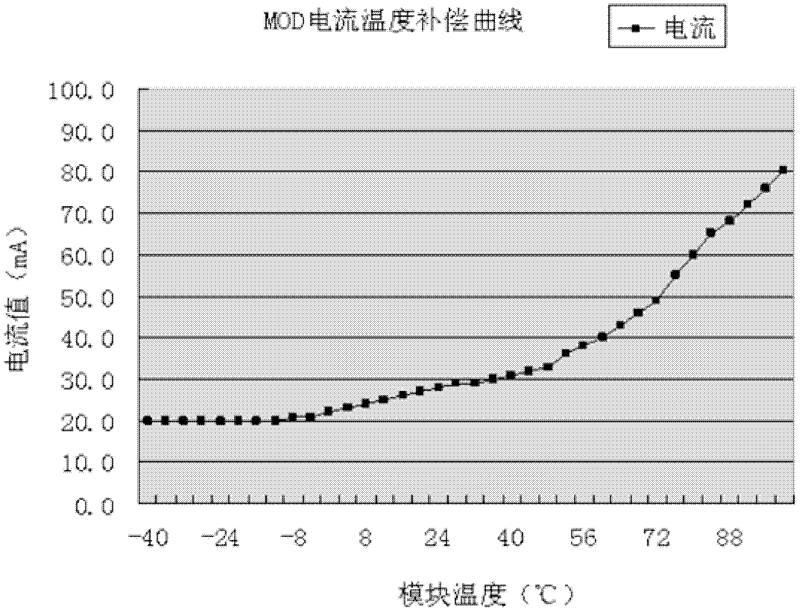
It can be seen that the low-temperature area of ​​the curve is relatively flat, and the high-temperature area is relatively steep, and it will increase without limit with the increase of the working temperature of the module, which is not good for the driving circuit of the laser, and will cause the temperature of the module laser to continue to rise, forming an unfavorable positive feedback loop

Method used


Image

  • Intelligent guarantee method for optical module in high temperature environment
  • Intelligent guarantee method for optical module in high temperature environment
  • Intelligent guarantee method for optical module in high temperature environment

Examples


Embodiment Construction

[0017] Below in conjunction with accompanying drawing and specific embodiment, further illustrate the present invention, should understand that following specific embodiment is only for illustrating the present invention and is not intended to limit the scope of the present invention, after having read the present invention, those skilled in the art will understand the present invention Modifications in various equivalent forms fall within the scope defined by the appended claims of the present application.

[0018] This design uses industrial-grade MCU + integrated dedicated IC solution;

[0019] Integrated IC is a dedicated chip for optical modules that integrates laser drivers and limiting amplifiers. It has built-in multiple function control registers and standard I 2 C (two-wire serial communication protocol) communication interface, can be fully digitally adjusted and set through an external microcontroller.

[0020] Industrial-grade MCU Choose an industrial-grade MCU (...


PUM


Abstract

The invention discloses an intelligent guarantee method for an optical module in a high temperature environment. The method comprises the following steps of: setting the highest set temperature for the optical module; when the optical module works in the high temperature environment, tracking and sampling the working temperature and the working current of the optical module; when the working temperature of the optical module exceeds the highest set temperature, stopping increasing the working current of a laser, so that the working temperature of the optical module does not increase any longer; setting the maximum current value for the working current of the laser; and when the working current of the laser exceeds the maximum current value, revising the working current of the laser into the maximum current value, so as to protect the optical module at high temperature.

Description

technical field [0001] The invention relates to a control method, in particular to a guarantee control method for an optical module in a high-temperature environment. Background technique [0002] The existing optical module is controlled by a hardware APC (automatic optical power control loop) circuit to ensure the stability of the optical module's luminous power in the full temperature range. In the high temperature environment, the luminous power of the optical module decreases due to the decrease of the luminous efficiency of the laser, and the feedback signal received by the hardware APC control loop decreases. The APC control loop will automatically increase the laser operating current to control the luminous power to be stable. The increase of the current will lead to the increase of the power consumption of the optical module itself, the further increase of the operating temperature, the decrease of the laser luminous efficiency of the optical module, the reduction o...

Claims


Application Information

Patent Timeline
Patent Type & Authority Applications(China)
IPC IPC(8): H01S3/131G05B19/401
Inventor 于佩简小忠
Owner JIANGSU ALLRAY
Why Eureka
Eureka Blog
Learn More