
Separable transformer with magnetic core in nested structure

A nested structure and transformer technology, applied in the direction of transformer/inductor magnetic core, etc., can solve the problems of uneven magnetic flux inside the magnetic core, leakage of high-frequency magnetic field, and easy saturation of the magnetic core, so as to improve efficiency and transmit power capacity , The effect of reducing the leakage of high-frequency magnetic field and increasing the excitation inductance

Inactive Publication Date: 2012-02-22
FUZHOU UNIV
View PDF4 Cites 9 Cited by
  • Summary
  • Abstract
  • Description
  • Claims
  • Application Information

AI Technical Summary

Problems solved by technology

However, the structure is not standardized, and the processing of the magnetic core is not easy, and the external magnetic core makes the magnetic path length difference inside the magnetic core large, resulting in uneven magnetic flux inside the magnetic core, which may easily saturate the magnetic core
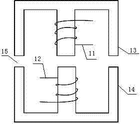
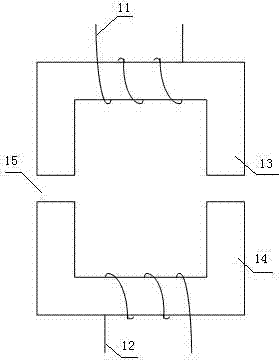
Figure 4 It is a separable transformer constructed with planar magnetic component technology. The primary coil 12 of the transformer is constructed as a platform by using an arrayed printed circuit board PCB, and the secondary coil 11 is placed on the platform. This structure can better solve the problem of power generation of portable electronic products The location of the power receiving end is random, but there are also problems of relatively small power transmission capacity and serious leakage of high-frequency magnetic field in areas without charging, which not only leads to serious electromagnetic interference, but also may induce fatal eddy current loss on portable electronic products and damage electronic equipment , and may damage human health

Method used


Image

  • Separable transformer with magnetic core in nested structure
  • Separable transformer with magnetic core in nested structure
  • Separable transformer with magnetic core in nested structure

Examples


Embodiment Construction

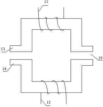
[0018] Refer to the attached Figure 5 , 6 , 7, and 8 describe in detail the implementation of the present invention, and the embodiment takes a UU-shaped magnetic core as an example. Such as Figure 5 As shown, this embodiment consists of a magnetic core 51 wound with a primary coil, a magnetic core 53 wound with a secondary coil, a bobbin 52 , a bobbin 54 , a primary coil 55 , a secondary coil 56 , and an air gap 57 . The structural assembly of the embodiment is that the skeleton 52 is set on the magnetic core 51 winding the primary coil, the primary coil 55 is wound on the skeleton 52, the skeleton 54 is sleeved on the magnetic core 53 winding the secondary coil, and the secondary The coil 56 is wound on the skeleton 54, and the magnetic core 53 wound on the secondary coil is nested in the magnetic core 51 wound on the primary coil, with an air gap 57 in the middle, and the air gap 57 can be formed by an air gap or Constructed of low magnetic permeability materials. Im...


PUM


Abstract

The invention relates to the field of manufacturing of magnetic elements, in particular to a power electronic high frequency power magnetic element. The invention provides a separable transformer with a magnetic core in a nested structure, the separable transformer comprises a high-permeability magnetic core, a skeleton sheathed on a magnetic core column, a coil wound on the skeleton and an air gap between the magnetic core, the separable transformer is characterized in that widths of magnetic cores which are respectively wound a primary coil and a secondary coil, are different, the magnetic cores which are wound the primary coil and the secondary coil of a transformer adopt nested assembly structure, and a major air gap is arranged between magnetic cores. The separable transformer provided by the invention can be used as a separable transformer of a non-contact charger, corresponding area between a primary magnetic core and a secondary magnetic core of the transformer can be effectively increased, and the separable transformer provided by the invention has the advantages of high coupling coefficient, low leakage inductance, high magnetizing inductance, uniform magnetic circuit ina magnetic core, high mechanical strength and convenience in production.

Description

technical field [0001] The invention belongs to the field of magnetic element manufacturing, in particular to power electronic high-frequency power magnetic elements. Background technique [0002] The non-contact charging technology based on the principle of electromagnetic induction coupling involves power electronic conversion, electromagnetic coupling and other technologies. Compared with the traditional contact charging technology, it can not only overcome the inherent problem of the existing charging technology because it can transmit electric energy without wire contact. Problems such as electric sparks, inconvenient connection and safety caused by contact are especially suitable for power supply occasions such as flammable, humid, moving objects (such as electric vehicles, etc.), implanted medical devices in the human body, and non-contact induction chargers It can also be conveniently embedded in occasions where power supply is required to realize power supply anytim...

Claims


Application Information

Patent Timeline
IPC IPC(8): H01F27/26H01F27/24
Inventor 毛行奎王自成
Owner FUZHOU UNIV
Learn More