Single-fiber bidirectional transceiving module and package thereof
A single-fiber bidirectional transceiver and installation technology, which is applied in optics, lenses, instruments, etc., can solve problems such as conflicts, large volume of optical transceiver modules, and large structural size of single-fiber bidirectional components, and achieve high output power and extended focal length , the effect of size reduction
- Summary
- Abstract
- Description
- Claims
- Application Information
AI Technical Summary
Problems solved by technology
Method used
Image

Examples
Embodiment 1
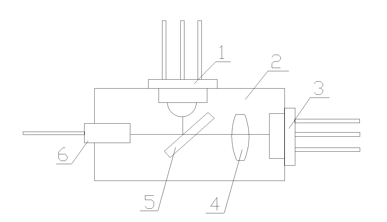
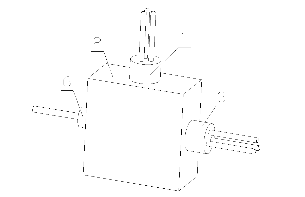
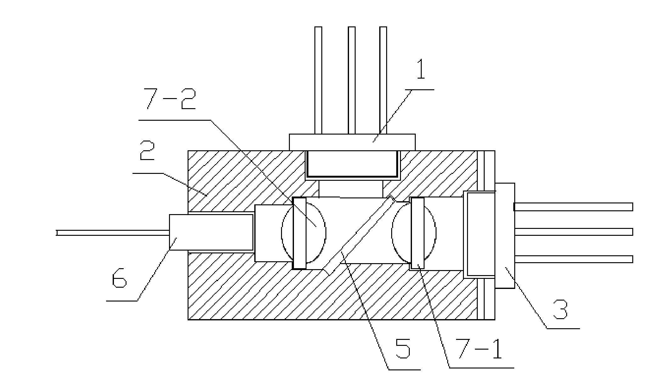
[0050] see figure 2 , image 3 The shown single-fiber bidirectional transceiver module includes a first aspheric lens 7-1, a second aspheric lens 7-2 and a beam splitter 5, the beam splitter 5 is set at an inclination angle of 45° in the optical path, and the first aspheric lens 7 -1, the plane of the second aspheric lens 7-2 is vertically arranged on both sides of the beam splitter 5; the two ends of the beam splitter 5 are connected to the first aspheric lens 7-1 and the second aspheric lens 7- 2 without contact; the laser diode 3 is placed at the focus of the first aspheric lens 7-1, and the photodiode 1 is placed at the focus of the second aspheric lens 7-2. The encapsulation 2 applied to the light-emitting module (such as Figure 6 shown), including a laser diode installation end 2-2, a photodiode installation end 2-4 and an optical fiber installation end 2-5, and the inside of the package 2 has a cavity 9 corresponding to the beam splitter 5 and the aspheric lens; the...
Embodiment 2
[0053] see figure 2 , Figure 4 The shown single-fiber bidirectional transceiver module includes a first ball lens 8-1, a second aspheric lens 7-2 and a beam splitter 5, the beam splitter 5 is set at an inclination angle of 60° in the optical path, and the first ball lens 8-1 Be arranged on one side of the beam splitter 5, the plane of the second aspheric lens 7-2 is vertically arranged on the other side of the beam splitter 5; wherein the laser diode 3 is placed at the focal point of the first ball lens 8-1, The photodiode 1 is placed at the focal point of the second aspheric lens 7-2. The encapsulation 2 applied to the light-emitting module (such as Figure 7 Shown), including laser diode mounting end 2-2, photodiode mounting end 2-4, optical fiber mounting end 2-5, inside package 2 there are beam splitter 5, first ball lens 8-1, second aspheric surface The corresponding cavity 9 of lens 7-2 and beam splitter 5; The receiving groove 2-7 matching the lower end of 5; the ...
Embodiment 3
[0056] see figure 2 , Figure 5 The shown single-fiber bidirectional transceiver module includes a first aspherical lens 7-1, a second ball lens 8-2 and a beam splitter 5, the beam splitter 5 is set at an inclination angle of 45° in the optical path, and the second ball lens 8-2 It is arranged on one side of the beam splitter 5, and the plane of the first aspheric lens 7-1 is vertically arranged on the other side of the beam splitter 5; wherein the laser diode 3 is placed at the focal point of the first aspheric lens 7-1 , the photodiode 1 is placed at the focal point of the second ball lens 8-2. The encapsulation 2 applied to the light-emitting module (such as Figure 8 Shown), including laser diode mounting end 2-2, photodiode mounting end 2-4, optical fiber mounting end 2-5, the interior of package 2 has beam splitter 5, first aspheric lens 7-1, second ball The corresponding cavity 9 of lens 8-2 and beam splitter 5; The second receiving groove 2-7 matching the lower en...
PUM
 Abstract
Description
Claims
Application Information
 - Generate Ideas
- Intellectual Property
- Life Sciences
- Materials
- Tech Scout
- Unparalleled Data Quality
- Higher Quality Content
- 60% Fewer Hallucinations
Browse by: Latest US Patents, China's latest patents, Technical Efficacy Thesaurus, Application Domain, Technology Topic, Popular Technical Reports.
© 2025 PatSnap. All rights reserved.Legal|Privacy policy|Modern Slavery Act Transparency Statement|Sitemap|About US| Contact US: help@patsnap.com