
Light diffusing element, polarizing plate with light diffusing element, liquid crystal display using both, and manufacturing method for light diffusing element

A manufacturing method and light diffusion technology, which are applied to semiconductor devices of light-emitting elements, optical elements, and parts of lighting devices, etc., can solve the problems of complex manufacturing process, insufficient productivity, and impractical use of fine particles, and achieve the goal of suppressing backlash. Scattering, cost-effective, and the effect of widening the difference in refractive index

Inactive Publication Date: 2012-02-15
NITTO DENKO CORP
View PDF15 Cites 26 Cited by
  • Summary
  • Abstract
  • Description
  • Claims
  • Application Information

AI Technical Summary

Problems solved by technology

However, these granules have a complicated manufacturing process compared with ordinary granules, so productivity is not sufficient, so it is not practical to use these granules

Method used


Image

  • Light diffusing element, polarizing plate with light diffusing element, liquid crystal display using both, and manufacturing method for light diffusing element
  • Light diffusing element, polarizing plate with light diffusing element, liquid crystal display using both, and manufacturing method for light diffusing element
  • Light diffusing element, polarizing plate with light diffusing element, liquid crystal display using both, and manufacturing method for light diffusing element

Examples


Embodiment 1

[0144]

[0145] To 18.2 parts of hard coat resin (manufactured by JSR Corporation, trade name "Opstar KZ6661" (containing MEK / MIBK) was added 6.8 parts of 50% methyl ethyl ketone (MEK ) solution, 0.068 parts of photopolymerization initiator (manufactured by Ciba Specialty Chemicals, trade name "Irgacure 907"), 0.625 parts of leveling agent (manufactured by DIC Corporation, trade name "GRANDIC PC 4100"), and 2.5 parts of polymethyl methacrylate (PMMA) fine particles (manufactured by Soken Chemical Co., Ltd., trade name "MX 180 TA", average particle diameter 1.8 μm, refractive index 1.49) as light diffusing fine particles. The mixture was ultrasonically processed for 5 minutes to prepare a coating solution that was uniformly dispersed with the above-mentioned components. The solid content of the coating solution was 54.5%. After preparing the coating solution, the coating solution was immediately coated with a rod machine-coated on a TAC film (manufactured by Fuji Photo Film...

Embodiment 2

[0147]

[0148] Except having changed the coating thickness of the coating liquid, it carried out similarly to Example 1, and obtained the light-diffusion element of thickness 16 micrometers. The obtained light-diffusing element was used for the evaluation of said (1)-(6). The results are shown in Table 1.

Embodiment 3

[0149]

[0150] Except having changed the coating thickness of the coating liquid, it carried out similarly to Example 1, and obtained the light-diffusion element of thickness 4 micrometers. The obtained light-diffusing element was used for the evaluation of said (1)-(6). The results are shown in Table 1.


PUM


Abstract

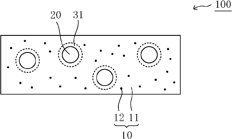
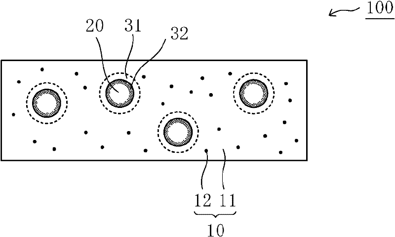
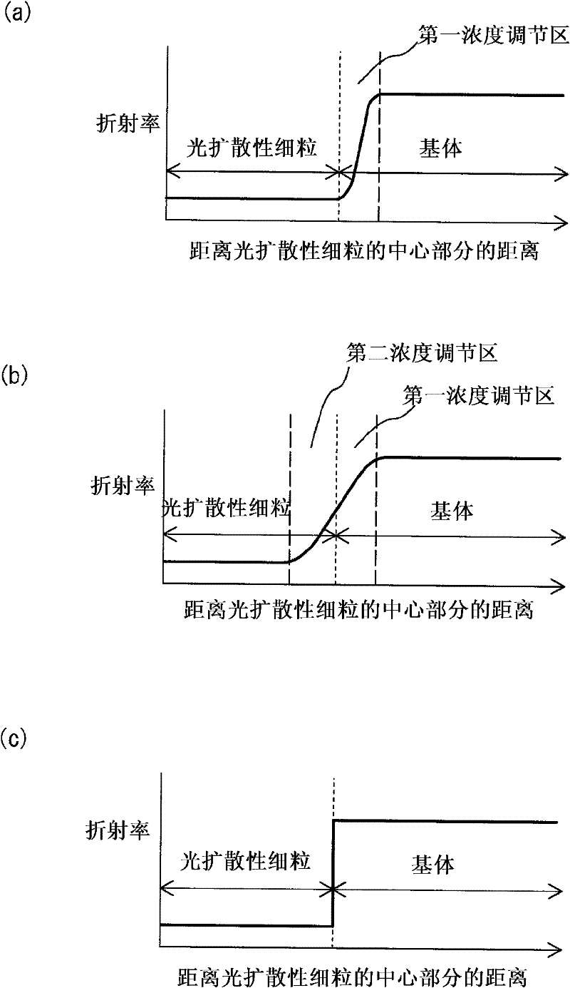
Provided is a light diffusing element that has a high haze value and strong diffusion characteristics with limited backscatter, and can be produced at a low cost. The light diffusing element has a matrix that includes a resin component and an ultra-fine particle component, and light diffusing micro particles dispersed within said matrix, wherein said resin component, said ultra-fine particle component, and said light diffusing micro particles fulfill the conditions of a formula (1) below, and has a concentration adjusted area that is formed near the interface of said matrix and said light diffusing micro particles wherein the weight concentration of said resin component becomes progressively lower and the weight concentration of said ultra-fine particle component becomes progressively higher with distance from said light diffusing particles. (1) |nP-nA|P-nB| In formula (1), nA represents the refractive index of the resin component in the matrix, nB represents the refractive index of the ultra-fine particle component in the matrix, and nP represents the refractive index of the light diffusing micro particles.

Description

technical field [0001] The present invention relates to a light diffusing element, a polarizing plate having the light diffusing element, a liquid crystal display device using them, and a method for manufacturing the light diffusing element. Background technique [0002] Light diffusing elements are widely used in lighting lampshades, screens of rear projection TVs, surface emitting devices (eg, liquid crystal display devices), and the like. In recent years, the utilization of a light-diffusion element for the improvement of display quality of a liquid crystal display device etc., improvement of a viewing angle characteristic, etc. is advancing, for example. As a light-diffusing member, for example, a light-diffusing member in which fine particles are dispersed in a matrix such as a resin sheet has been proposed (for example, refer to Patent Document 1). In such a light diffusing element, most of the incident light is scattered forward (on the exit surface side), and a part...

Claims


Application Information

Patent Timeline
Patent Type & Authority Applications(China)
IPC IPC(8): G02B5/02F21V3/04G02B5/30G02F1/1335G03B21/62B82Y20/00F21V3/00F21Y115/10F21Y115/20
CPCG02B5/0242G02B5/3033G03B21/62G02B5/02G02B5/30G02F1/1335
Inventor 渊田岳仁武本博之首藤俊介宫武稔
Owner NITTO DENKO CORP
Learn More