
Commutation failure detection method based on commutating current time area index

A technology of commutation failure and detection method, applied in the direction of the fault location, etc., can solve the problems of commutation failure of the converter station, grid instability, system operation collapse, etc.

Active Publication Date: 2012-02-15
SICHUAN UNIV
View PDF1 Cites 51 Cited by
  • Summary
  • Abstract
  • Description
  • Claims
  • Application Information

AI Technical Summary

Problems solved by technology

[0004] Commutation failure will lead to a drop in DC voltage and an increase in DC current. If improper control measures are taken, subsequent commutation failures will also occur. In severe cases, the DC transmission power will be interrupted, making the entire system unstable and affecting the safe operation of the power grid. significant impact
Compared with the single-infeed DC transmission system, the multi-infeed HVDC system has a larger transmission capacity and a more flexible operation mode, but it also brings some special problems. The phase failure is more sensitive, and the research on the commutation failure problem will be more complicated
A commutation failure of a converter station will not only cause voltage fluctuations in its own DC system, but may also cause commutation failures in multiple nearby converter stations, and even cause the entire system to collapse.
In recent years, the power grid has experienced extraordinary development, and many DC lines have been put into operation one after another. However, the mixed operation mode of AC and DC is generally adopted in the regional networking. The transfer will make the relevant lines overloaded, which will have a direct impact on the stable operation of the AC system. If multiple DC lines have cascading failures, it may even lead to grid instability.

Method used


Image

  • Commutation failure detection method based on commutating current time area index
  • Commutation failure detection method based on commutating current time area index
  • Commutation failure detection method based on commutating current time area index

Examples


Embodiment

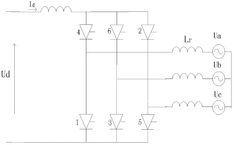
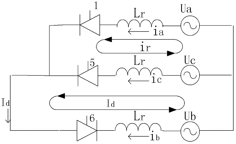
[0044] 1. Overview of commutation failure mechanism

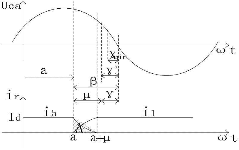
[0045] According to the definition of commutation failure, it mainly expounds two situations that lead to commutation failure: one is that the valve that has just exited conduction fails to recover the blocking ability (γ<γmin) during the reverse voltage action, when the valve voltage When it turns to positive direction, the valve that was originally withdrawn from conduction does not need a trigger pulse to conduct again; the second is that the valve that needs to withdraw from conduction fails to complete the commutation process during the reverse voltage period, and the valve remains in conduction all the time without being turned off. On state, when the valve voltage changes to positive, it will continue to conduct.

[0046] Through the understanding of the definition, it can be found that the key to the commutation failure is not the size of the arc-extinguishing angle γ, but the size of the commutation angle μ during ...


PUM


Abstract

The invention discloses a commutation failure detection method based on a commutating current time area index. The commutation failure detection method is characterized in that a conception of the commutating current time area is provided for a commutation process of an inversion side of a convertor station for a direct current system according to an area defined by commutating current and a timeaxis; the physical significance of the commutation process is disclosed in terms of energy by a commutating current time area method; corresponding criteria are provided according to the magnitude ofthe commutating current time area; and the criteria can be used as a new index for correctly judging whether the inversion side of the convertor station has commutation failure or not.

Description

technical field [0001] The invention relates to a commutation failure detection method based on a commutation current time area index, which belongs to the field of high voltage direct current transmission. Background technique [0002] Commutation failure is one of the most common faults during the inverter operation of the HVDC converter station. The main reason for its occurrence is that the commutation voltage drops due to the failure of the AC system on the inverter side. In some cases, the commutation failure may recover by itself, but continuous commutation failure may cause the DC transmission system to block, and even endanger the stability of the entire system, causing greater harm. In the AC-DC hybrid operation system, the voltage collapse and the control-induced voltage oscillation will cause permanent commutation failure of the inverter. [0003] Commutation failure refers to: when the commutation between the two bridge arms is over, if the valve that has just ...

Claims


Application Information

Patent Timeline
IPC IPC(8): G01R31/08
Inventor 王渝红李思思李兴源魏巍何鹏飞戴寒光邓鸿强
Owner SICHUAN UNIV
Learn More