Eureka AIR delivers breakthrough ideas for toughest innovation challenges, trusted by R&D personnel around the world.

Method of correction for non-contact thermometry in translucent medium environment

A translucent medium, non-contact temperature measurement technology, used in thermometer testing/calibration, thermometers, measuring devices, etc.

Active Publication Date: 2012-02-15
HARBIN INST OF TECH
View PDF2 Cites 25 Cited by
  • Summary
  • Abstract
  • Description
  • Claims
  • Application Information

AI Technical Summary

Problems solved by technology

[0005] The purpose of the present invention is to solve the problem that the radiation energy detected by the traditional method cannot be corrected by the traditional material surface emissivity correction method to obtain its real temperature when the surface of the measured object is covered by a translucent medium. Calibration method of non-contact temperature measurement in translucent medium environment

Method used


Image

  • Method of correction for non-contact thermometry in translucent medium environment
  • Method of correction for non-contact thermometry in translucent medium environment
  • Method of correction for non-contact thermometry in translucent medium environment

Examples


specific Embodiment approach 1

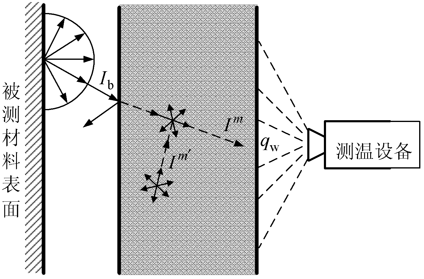
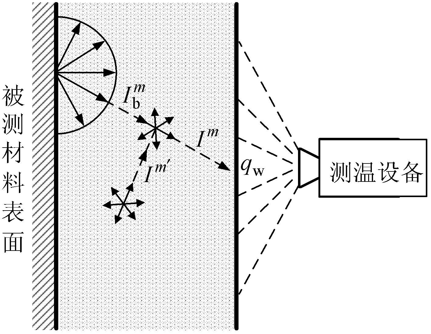
[0067] Specific implementation mode one: the following combination Figure 1 to Figure 3 Describe this embodiment, the correction method for non-contact temperature measurement in a translucent medium environment described in this embodiment, it includes the following steps:

[0068] Step 1: Determine whether the translucent medium is in contact with the surface of the material to be tested, if so, perform step 2; otherwise, perform step 3;

[0069] Step 2: Select a one-dimensional coupled heat transfer model, use the finite volume method to calculate the forward model, and obtain the theoretical radiation energy value that the temperature measurement equipment can obtain, and then perform step 4;

[0070] Step 3: Select a one-dimensional pure radiation heat transfer model, use the finite volume method to calculate the forward model, obtain the theoretical radiation energy value that the temperature measuring equipment can obtain, and then perform step 4;

[0071] Step 4: Use...

specific Embodiment approach 2

[0074] Specific implementation mode two: the following combination figure 1 and image 3 This embodiment is described. This embodiment is a further description of Embodiment 1. The specific method for obtaining the theoretical radiation energy value of the measuring device in step 2 is:

[0075] Choose a one-dimensional coupled heat transfer model, and divide the interior of the translucent medium into grids along the direction perpendicular to the surface of the material to be tested according to the calculation accuracy requirements, and divide them into multiple grid units evenly, and use the zenith angle and horizontal angle to evenly divide The method discretely divides the solid angle of the internal space of the translucent medium into N Ω , the grid unit is parallel to the surface of the measured material; set the radiation source term q R The initial value of is 0, using the energy conservation equation of the one-dimensional coupled heat transfer model and the coup...

specific Embodiment approach 3

[0105] Specific implementation mode three: the following combination figure 1 with figure 2 This embodiment is described. This embodiment is a further description of Embodiment 1. The specific method for obtaining the theoretical radiation energy value of the temperature measuring device in step 3 is:

[0106] Suppose the temperature of the surface of the material to be measured is T w , according to the spectral emissivity ε of the surface of the measured material k Calculation of the outgoing radiation intensity from the surface of the material under test

[0107] I 0 , k m = ϵ k σT w 4 π , - - - ( 10 )

[0108] will emit ra...


PUM


Abstract

The invention relates to a method of correction for non-contact thermometry in a translucent medium environment, which belongs to the technical field of pyrometry. The problem that when the surface of an object to be measured is in a translucent medium coverage environment, radiation energy detected through a traditional method can not be corrected through a traditional material surface emissivity correction method, so that the actual temperature can not be obtained is solved. The method comprises the following steps of: firstly, judging whether a translucent medium is contacted with the surface of the object to be measured, if so, selecting a one-dimensional coupling heat exchange model, adopting a finite volume method to calculate a forward model, and obtaining a theoretical radiation energy value capable of being obtained by temperature measuring equipment; if not, selecting a one-dimensional pure radiation heat exchange model, adopting the finite volume method to calculate the forward model, and obtaining the theoretical radiation energy value capable of being obtained by the temperature measuring equipment; then measuring an actual radiation energy value of the surface of theobject to be measured; and adopting an intelligent particle swarm optimization algorithm to inverse an actual temperature value of the surface of the object to be measured. The method provided by theinvention is applied to temperature measurement of the surface of the object to be measured in the translucent medium environment.

Description

technical field [0001] The invention relates to a correction method for non-contact temperature measurement in a translucent medium environment, belonging to the technical field of high temperature measurement. Background technique [0002] Temperature is one of the most important parameters to determine the state of matter. The measurement and control of temperature plays a very important role in national defense, military, scientific experiments and industrial and agricultural production, especially high temperature measurement, in aerospace, materials, energy, metallurgy, etc. field plays a very important role. [0003] Temperature measurement can be roughly divided into two categories: contact method measurement and non-contact method measurement. The contact method of temperature measurement includes thermocouple temperature measurement and thermal resistance temperature measurement, etc., and the non-contact method of temperature measurement is mainly based on radiati...

Claims


Application Information

Patent Timeline
Patent Type & Authority Applications(China)
IPC IPC(8): G01K15/00
Inventor 齐宏张彪阮立明谈和平
Owner HARBIN INST OF TECH
Why Eureka
Eureka Blog
Learn More