Heat pump hot-water supply floor heating device

A heating system and hot water technology, applied in heating systems, hot water central heating systems, heating methods, etc., can solve problems such as detachment or imbalance of the compression mechanism, reduced reliability, low operating efficiency, etc., to reduce refrigerant Effects of reducing load, improving reliability, and improving operating efficiency

Inactive Publication Date: 2012-02-15
HITACHI APPLIANCES INC +1
View PDF1 Cites 0 Cited by
  • Summary
  • Abstract
  • Description
  • Claims
  • Application Information

AI Technical Summary

Problems solved by technology

Moreover, although the compressor is designed to meet the requirements of hot water supply with its maximum capacity, it is operated at a low speed during the floor heating operation when the ambient temperature is high, so that the turbo compression mechanism is abnormal due to detachment, imbalance, etc. The main cause of abnormal conditions such as extreme reduction in capacity or noise caused by the situation, and may reduce the reliability
[0011] That is, since there is a large difference between the heating capacity required for hot water supply operation and the heating capacity required for floor heating, the existing compressor speed control cannot meet the requirements. , there may be problems such as detachment or misalignment of the compression mechanism, noise, etc.
[0012] On the other hand, from the point of view of energy saving, when the heat pump operates at a constant water supply temperature, the higher the temperature of the heated and released hot water, the lower the operating efficiency. The faucet supplies hot water and the floor is heated by heat pump operation under the condition of low operating efficiency
[0013] Furthermore, since a large amount of high-temperature hot water is stored in the hot water storage tank, energy loss due to heat dissipation is also a big problem.

Method used


Image

  • Heat pump hot-water supply floor heating device
  • Heat pump hot-water supply floor heating device
  • Heat pump hot-water supply floor heating device

Examples


Embodiment 1

[0035] Below, according to Figure 1-Figure 6 A first embodiment of the present invention will be described.

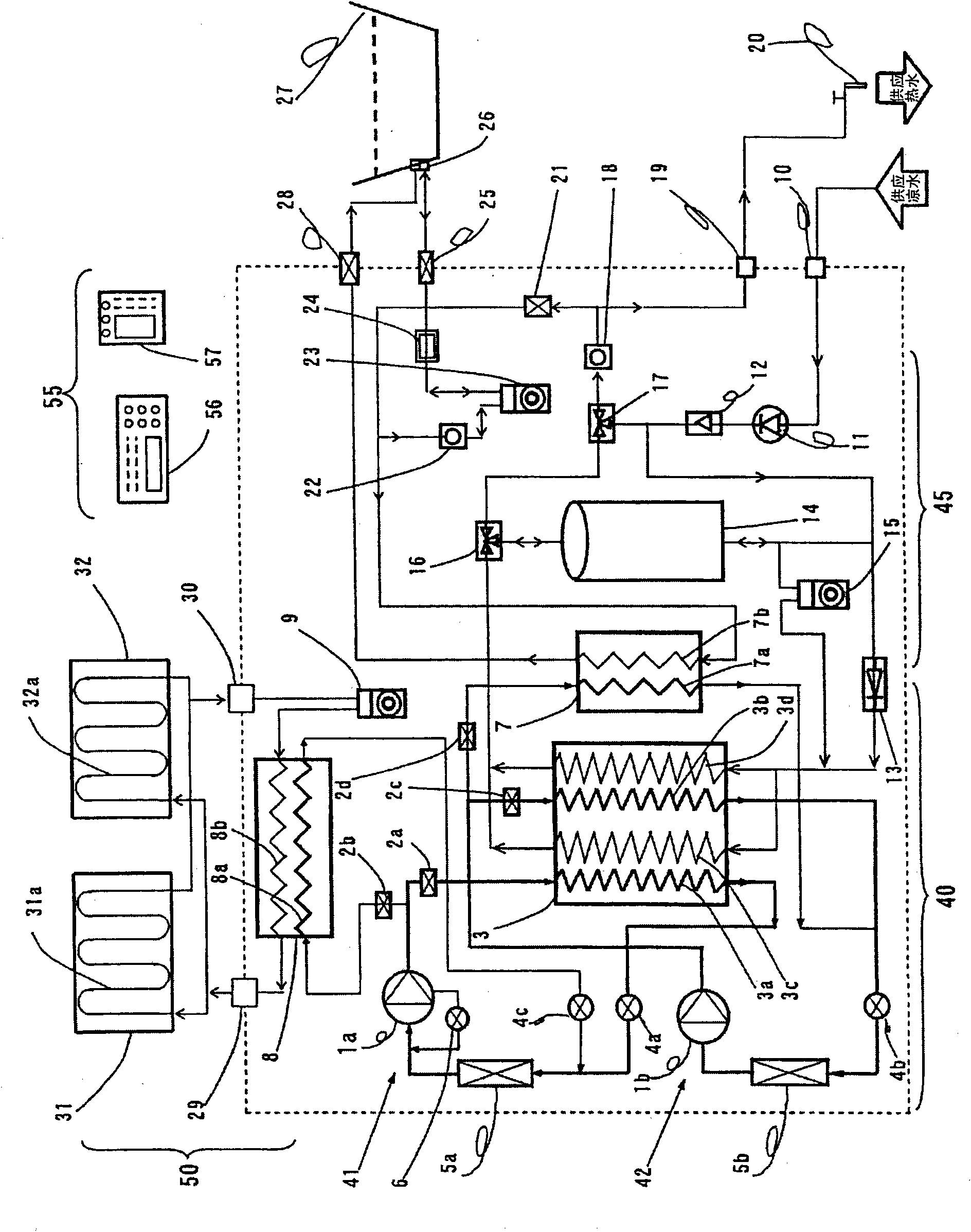
[0036] figure 1 Among them, the structure of the heat pump hot water supply type floor heating system has: a heat source circuit 40 composed of two heat pump refrigerant circuits of the floor heating side refrigerant circuit 41 and the bath water side refrigerant circuit 42, and a hot water supply circuit 45 , the floor heating heat exchanger 8 and the operation control device 55 as constituent members of the floor heating circuit 50 .

[0037] The heat source circuit 40, the hot water supply circuit 45, and the floor heating heat exchanger 8 are integrally accommodated in the same box, and the operation control device 55 is composed of a separate kitchen remote control 56 and bath water remote control 57.

[0038] In addition, the floor heating devices 31 and 32 as the constituent parts of the above-mentioned floor heating circuit 50 are installed separately from t...

Embodiment 2

[0094] Below, according to Figure 7 A second embodiment of the present invention will be described.

[0095] Figure 7 in, with figure 1 There are three different components: a heating water pipe 37a on the heating side of the bath water heat exchanger 37, a heating water switch valve 35 for switching the heating water flowing to the heating water pipe 37a, and a heat exchange valve 35 for detecting and supplying hot water. The flow sensor 36 for heat exchange of the flow rate of the device 3 .

[0096] Figure 7 in, with in figure 1 The point of difference of the first embodiment described in the above is that the refrigerant pipe 7a for bath water used as the heating side of the heat exchanger 7 for bath water is replaced with the water heating pipe 37a; the water pipe 37a for heating is used to make the slave The hot water supplied by the water supply side heat transfer pipes 3 c and 3 d heated by the heat exchanger 3 flows through the hot water flowing in through the...


PUM


Abstract

The invention aims to solve a problem where, although a direct hot-water supply type is being considered in order to reduce size and weight in a heat pump hot-water supply floor heating device having a floor heating function at the same time, the difference between necessary heating capability in a hot-water supply operation and that in a floor heating operation is large, it can not be handled by conventional control of the number of revolutions of a compressor, and, in particular, separation, loss of synchronism, noise and the like of a compression mechanism part are generated in a low-speed operation in the floor heating operation. The heat pump hot-water supply floor heating device provided by the invention solves the problem of the prior art by executing a heat pump operation in using hot water, by adding a floor heating function to a direct hot-water supply type heat pump water heater for directly supplying heating water to a used terminal, and by skillfully using control of the number of revolutions and capacity control as a control method of a compressor.

Description

[0001] This application is a divisional application of an invention patent application with the application number 200610008344.2, the application date being February 17, 2006, and the invention name being "heat pump supplying hot water floor heating system". technical field [0002] The present invention relates to a heat pump supplying hot water floor heating system, especially to provide a compressor capable of expanding the variation range of the capacity of the compressor, which can correspondingly realize the operation from supplying hot water with a large capacity to a small capacity operation with high operating efficiency. A heat pump running underfloor heating supplies a hot water underfloor heating system. Background technique [0003] In recent years, along with the popularity of heat pumps supplying water heaters, technical solutions with floor heating functions have been proposed. [0004] As such a heat pump water heater, there is, for example, one disclosed i...

Claims


Application Information

Patent Timeline
Patent Type & Authority Applications(China)
IPC IPC(8): F24D3/18F24D19/10
Inventor 店纲太一权守仁彦向井有吾幸野雄小山昌喜增田正水谷圭一
Owner HITACHI APPLIANCES INC
Why Eureka
Try Eureka